Isuzu D-Max / Isuzu Rodeo (TFR/TFS). Manual - part 1041


  Index      Ford     Isuzu D-Max / Isuzu Rodeo TFR/TFS series - service repair manual 1997-2003 year


Search            


Content   ..  1039  1040  1041  1042   ..


Isuzu D-Max / Isuzu Rodeo (TFR/TFS). Manual - part 1041


CLUTCH  7C-23

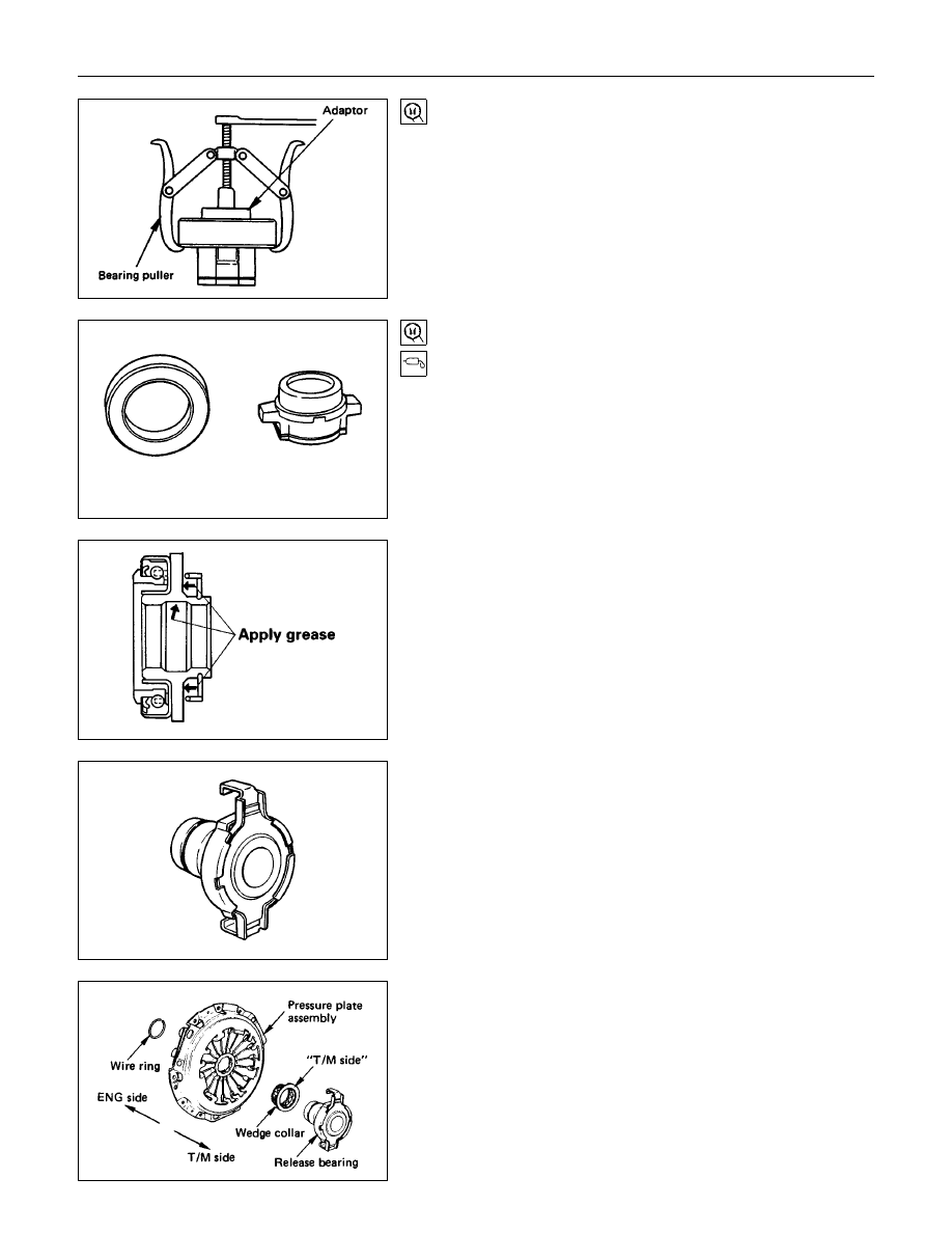
Release Bearing Replacement

Removal (Except 6VD1)

Use the bearing puller and the adapter to remove the release
bearing.
Bearing Puller : 5-8840-0013-0 (J-22888)
Adapter : 5-8840-0124-0 (J-2241-11)

Release Bearing Installation (Except 6VD1)

1. Set the release bearing to the shift block bearing fitting

surfaces.

The release bearing must be perfectly horizontal.

2. Use a bench press to fit the release bearing to the shift

block.

Install the parts as illustrated after applying wheel bearing
grease or multi-purpose type grease (NLGI No.2 or No.3).

6VD1

Release Bearing (6VD1)

1. Visually check the release bearing for excessive play, noise

and breakage.

If any of these conditions are discovered, the release

bearing must be replaced.

6VD1

NOTE:

When replacing the release bearing, replace both the
wedge collar and wire ring at the same time.

7C-24  CLUTCH

Wedge Collar (6VD1)

1. Visually check the surfaces of the wedge collar making

contact with the release bearing for excessive wear and

damage.

2. Replace any exhibiting excessive wear damage.

Shift Fork (Except 6VD1)

1. Visually inspect the surfaces of the shift fork making contact

with the shift block for excessive wear and damage.

2. Remove any minor stepping or abrasion from the shift block

with an oil stone.

Replace any exhibiting excessive wear or damage.

3. Apply multi-purpose type grease (NLGI No.2 or No.3) to

 area.

6VD1

Shift Fork (6VD1)

1. Visually check the surfaces of the shift fork making contact

with the release bearing for excessive wear and damage.

2. Remove any minor stepping or abrasion from shift fork with

an oil stone.

Replace any exhibiting excessive wear of damage.

DRIVEN PLATE ASSEMBLY

1. Visually inspect the torsion spring 

1

 for looseness,

breakage, and weakening.

If any of these conditions are discovered, the driven plate

assembly must be replaced.

2. Visually inspect the facing surfaces 

2

 for cracking and

excessive scorching.

Visually inspect the facing surfaces for the presence of oil or

grease.

If any of these conditions are discovered, the facing must be

cleaned or replaced.

CLUTCH  7C-25

3. Check that the driven plate moves smoothly on the

transmission top gear shaft spline.

Minor ridges on the top gear shaft spline may be removed

with an oil stone.

Driven Plate Warpage

1. Insert the clutch pilot aligner into the driven plate splined

hub.

The clutch pilot aligner must be held perfectly horizontal.

Clutch Pilot Aligner : 5-8840-2634-0 (HEC Engine Series)

5-8525-3001-0 (J-24547) (Except HEC Engine Series)

2. Set a dial indicator to the driven plate outside

circumference.

3. Slowly turn the driven plate.

Read the dial indicator as you turn the driven plate.

If the measured value exceeds the specified limit, the driven

plate assembly and/or the facing must be replaced.

Driven Plate Warpage

mm(in)

Standard

Limit

0.7 (0.028)

1.0 (0.039)

Driven Plate Splined Hub Spline Wear

1. Clean the driven plate splined hub.

2. Install the driven plate to the transmission top gear shaft

spline.

3. Set a surface gauge to the driven plate outside

circumference.

4. Slowly turn the driven plate counterclockwise.

Measure the spline rotation play as you turn the driven

plate.

If the measured value exceeds the specified limit, the driven

plate assembly must be replaced.

Driven Plate Splined Hub Spline Wear

mm(in)

Standard

Limit

0.5 (0.020)

1.0 (0.039)

7C-26  CLUTCH

Rivet Head Depression

Use a depth gauge or a straight edge with steel rule to
measure the rivet head depression 

1

 from the facing surface

2

.

Be sure to measure the rivet head depression on both sides of
the driven plate.
If the measured value is less than the specified limit, the facing
must be replaced.
Rivet Head Depression

mm(in)

Standard

Fly wheel side

P/Plate side

HEC

1.65

2.25

(0.065-0.089)

4JA1

1.35

1.95

(0.053-0.077)

1.65

2.25

(0.065-0.089)

0.2

(0.008)

4JB1T, 4JG2T

1.3

1.9

(0.051-0.075)

6VD1

1.6 (0.063)

Limit


Content   ..  1039  1040  1041  1042   ..