Content .. 1037 1038 1039 1040 ..
Isuzu D-Max / Isuzu Rodeo (TFR/TFS). Manual - part 1039
CLUTCH 7C-15
CLUTCH
REMOVAL AND INSTALLATION
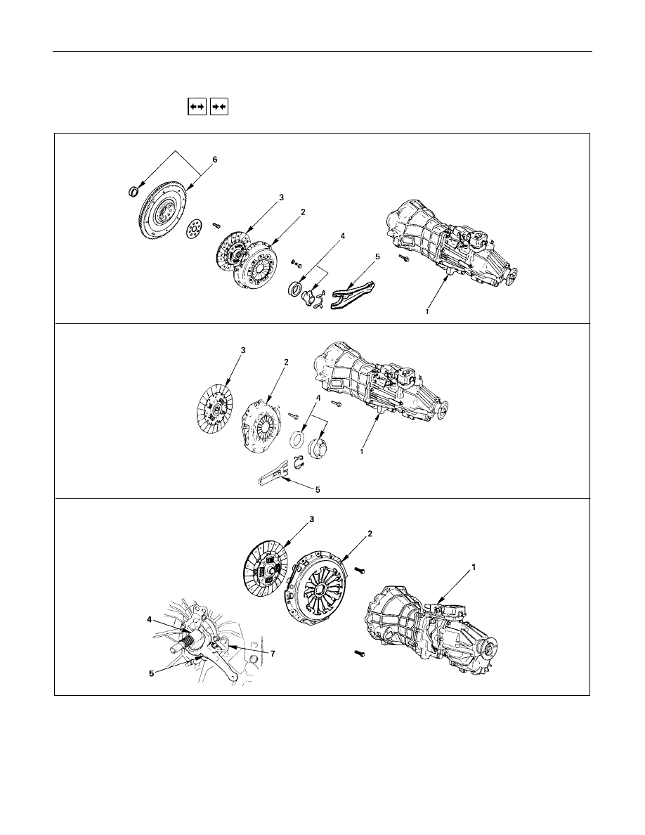
HEC Engine Series
4J Engine Series
6VD1
Removal Steps
1. Transmission assembly
▲
2. Pressure Plate assembly
▲
3. Driven plate assembly
4. Release bearing
5. Shift fork
6. Flywheel assembly and cran bearing
(HEC Engine Series)
7. Fulcrum bridge (6VD1)
Installation Steps
To install, follow the removal steps in the
reverse order.