Isuzu D-Max / Isuzu Rodeo (TFR/TFS). Manual - part 1007


  Index      Ford     Isuzu D-Max / Isuzu Rodeo TFR/TFS series - service repair manual 1997-2003 year


Search            


Content   ..  1005  1006  1007  1008   ..


Isuzu D-Max / Isuzu Rodeo (TFR/TFS). Manual - part 1007


10-28  CAB

10.Control Lever Assembly

1) Disconnect the control cable from heater unit and blower

unit.

2) Remove the control lever assembly fixing screws.
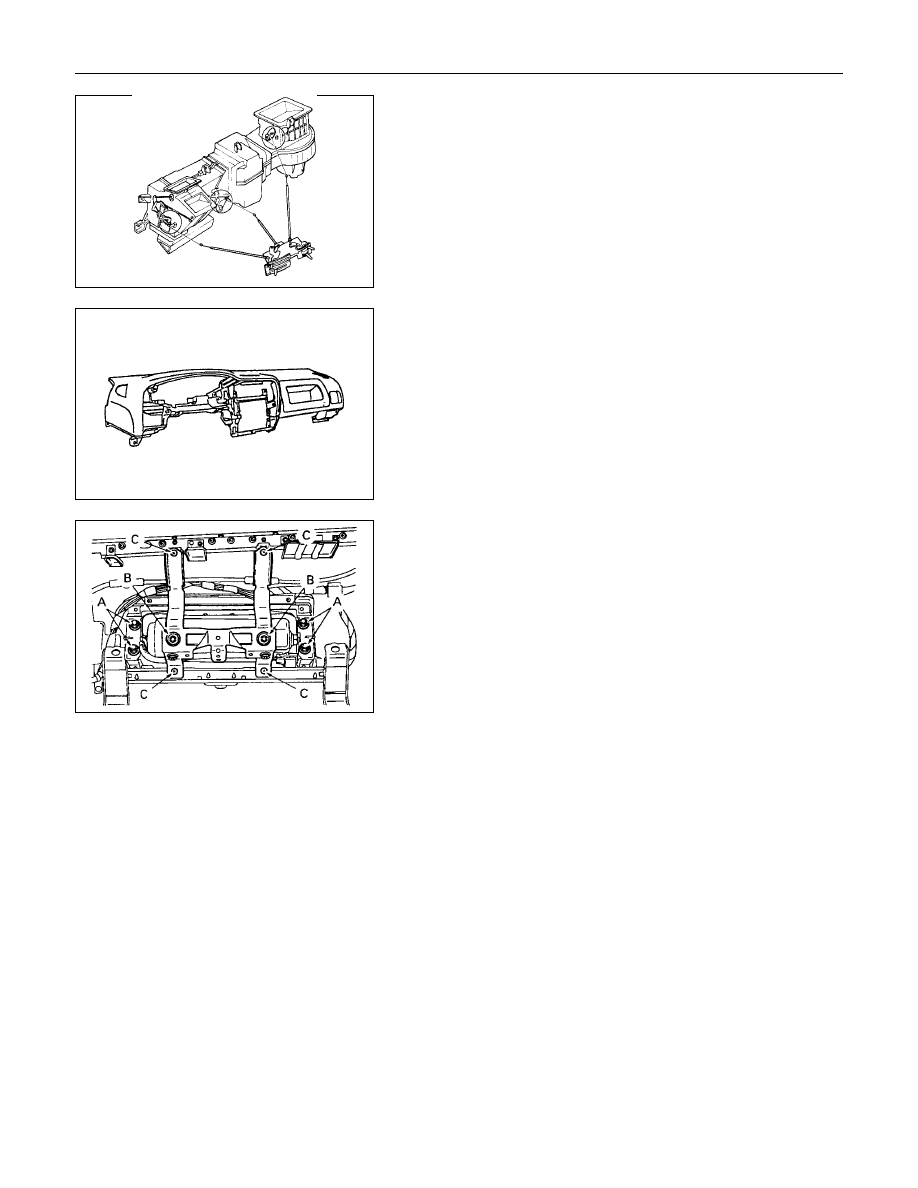
11.Instrument Panel

1) Remove the instrument panel fixing nuts and bolts.

2) Disconnect the instrument harness connectors.

3) Remove the instrument panel.

Caution:

For precautions on installation or removal of SRS-air bag
system, refer to section 9 "Supplemental Restraint System
(SRS) - AIR BAG".

12a. Passenger air bag assembly

Remove 4 fixing bolts A and 2 nuts B.

Caution:

For precautions on installation or removal of SRS-air bag
system, refer to section 9 "Supplemental Restraint System
(SRS) - AIR BAG".

13.Passenger air bag reinforcement assembly (W/SRS)

Remove 4 fixing screws C.

CAB  10-29

  INSTALLATION

Installation Steps

1. Radio assembly
2. Meter assembly
3. Passenger air bag reinforcement

assembly

4a. Passenger air bag
4b. Utility box
5. Instrument panel assembly

V

6. Control lever assembly
7. Instrument panel lower center cover

assembly

8. Meter cluster assembly

9. Lower cluster assembly

10. Instrument panel driver lower cover

assembly

11. Instrument panel passenger lower cover

assembly

12. Glove box cover
13. Glove box
14. Control unit cover
15. Center console assembly

10-30  CAB

Important Operation - Installation

6. Control Lever Assembly

1) Set the temperature control lever and the airsource

select lever at the left-hand side end.

2) Set the air selector lever at the right-hand side end.

1

 : Temperature control cable

2

: Air source select cable

3

: Air selector

3) Attach the cable, after the work 1) and 2) have been

completed.

CAB  10-31

CONSOLE BOX


  REMOVAL AND INSTALLATION

1

1

2

2

3

3

4

5

5

6

4

××××

4 S Model

Removal Steps

1. Hole cover 

×

2

2. Screw 

×

2

3. Screw 

×

2

4. Center console
5. Screw 

×

4

6. Rear console

Installation Steps

6. Rear console
5. Screw 

×

4

4. Center console
3. Screw 

×

2

2. Screw 

×

2

1. Hole cover 

×

2


Content   ..  1005  1006  1007  1008   ..