Infiniti G35 (V35). Manual - part 514


  Index      Infiniti     Infiniti G35 (V35) Coupe - service repair manual 2007 year


Search            


Content   ..  512  513  514  515   ..


Infiniti G35 (V35). Manual - part 514


FRONT SUSPENSION ASSEMBLY

FSU-5

C

D

F

G

H

I

J

K

L

M

A

B

FSU

FRONT SUSPENSION ASSEMBLY

PFP:54010

On-Vehicle Inspection

NES00023

Make sure the mounting conditions (looseness, back lash) of each component and component statues (wear,
damage) are normal.

INSPECTION OF BALL JOINT END PLAY OF EACH LINK

1.

Set front wheels in a straight-ahead position. Do not depress brake pedal.

2.

Check ball joint axial end play of each link.

CAUTION:

Be careful not to damage ball joint boot.

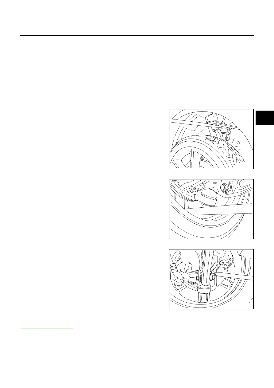
Upper Link Ball Joint

Measure axial end play by installing and moving up/down with an
iron pry bar or something similar between upper link and steering
knuckle.

Steering Knuckle Lower Ball Joint

Measure axial end play by installing and moving up/down with an
iron pry bar or something similar between steering knuckle and
wheel.

Compression Rod Ball Joint

Measure axial end play by installing and moving up/down with an
iron pry bar or something similar between compression rod and
transverse link.

SHOCK ABSORBER INSPECTION

Check shock absorber for oil leakage, damage and replace if necessary. Refer to 

FSU-11, "INSPECTION

AFTER DISASSEMBLY"

 .

Axial end play

: 0 mm (0 in)

SEIA0242J

Axial end play

: 0 mm (0 in)

SEIA0243J

Axial end play

: 0 mm (0 in)

SEIA0244J

FSU-6

FRONT SUSPENSION ASSEMBLY

Wheel Alignment Inspection

NES000DP

DESCRIPTION

Measure wheel alignment under unladen conditions.

NOTE:
Unladen conditions mean that fuel, engine coolant, and lubricant are full. Spare tire, jack, hand tools and
mats are designated positions.

PRELIMINARY CHECK

Check tires for improper air pressure and wear.

Check road wheels for runout.

Check wheel bearing axial end play.

Check ball joint axial end play of compression rod, upper link, and steering knuckle. 

Check shock absorber operation.

Check each mounting part of axle and suspension for looseness and deformation.

Check each link, rod and member for cracks, deformation and other damage.

Check vehicle posture.

GENERAL INFORMATION AND RECOMMENDATIONS

A four-wheel thrust alignment should be performed.

This type of alignment is recommended for any NISSAN/INFINITI vehicle.

The four-wheel “thrust” process helps ensure that the vehicle is properly aligned and the steering wheel is
centered.

The alignment rack itself should be capable of accepting any NISSAN/INFINITI vehicle.

The rack should be checked to ensure that it is level.

Make sure the machine is properly calibrated.

Your alignment equipment should be regularly calibrated in order to give correct information.

Check with the manufacturer of your specific equipment for their recommended Service/Calibration
Schedule.

FRONT SUSPENSION ASSEMBLY

FSU-7

C

D

F

G

H

I

J

K

L

M

A

B

FSU

THE ALIGNMENT PROCESS

IMPORTANT:
Use only the alignment specifications listed in this Service Manual.

When displaying the alignment settings, many alignment machines use “indicators”: (Green/red, plus or
minus, Go/No Go). Do not use these indicators.

The alignment specifications programmed into your machine that operate these indicators may not be cor-
rect.

This may result in an ERROR.

Some newer alignment machines are equipped with an optional “Rolling Compensation” method to “com-
pensate” the sensors (alignment targets or head units). Do not use this “Rolling Compensation”
method.

Use the “Jacking Compensation Method”. After installing the alignment targets or head units, raise the
vehicle and rotate the wheels 1/2 turn both ways.

See Instructions in the alignment machine you're using for more information on this.

INSPECTION OF CAMBER, CASTER AND KINGPIN INCLINATION ANGLES

Camber, caster, kingpin inclination angles cannot be adjusted.

Before inspection, mount front wheels onto turning radius gauge. Mount rear wheels onto a stand that has
same height so vehicle will remain horizontal.

Using a CCK Gauge

Install the CCK gauge attachment [SST: KV991040S0 (

)] with the following procedure on wheel, then

measure wheel alignment.

1.

Remove three wheel nuts, and install the guide bolts to hub bolt.

2.

Screw the adapter into the plate until it contacts the plate tightly.

3.

Screw the center plate into the plate.

4.

Insert the plate assembly on the guide bolt. Put the spring in,
and then evenly screw the three guide bolt nuts. When fastening
the guide nuts, do not completely compress the spring.

5.

Place the dent of alignment gauge onto the projection of center
plate and tightly contact them to measure.

CAUTION:

If camber, caster, or kingpin inclination angle is outside
the standard, check front suspension parts for wear and
damage, and replace suspect parts if necessary.

King pin inclination angle is reference value, no inspec-
tion is required. (Due to the type of suspension, the king-
pin inclination angle cannot be measured correctly using a normal alignment tester.)

SEIA0240E

Camber, caster, kingpin inclination angles:

Refer to 

FSU-20, "SERVICE DATA AND SPECIFI-

CATIONS (SDS)"

 .

SEIA0241E

FSU-8

FRONT SUSPENSION ASSEMBLY

Components

NES00025

PEIA0063E


Content   ..  512  513  514  515   ..