Infiniti G35 (V35). Manual - part 475
FRONT TIMING CHAIN CASE
EM-55
C
D
E
F
G
H
I
J
K
L
M
A
EM
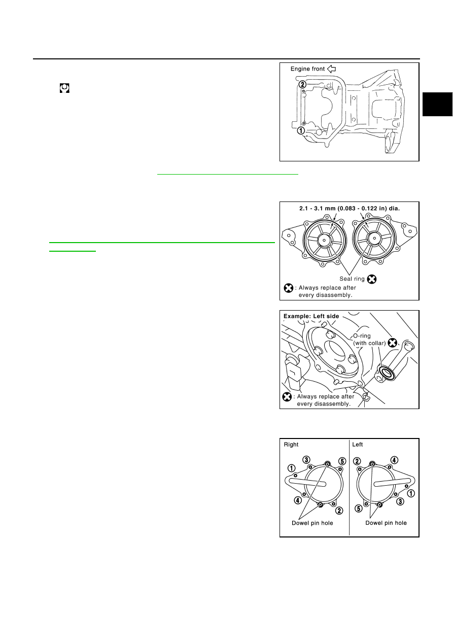
6.
Install two mounting bolts in front of oil pan (upper) in numerical
order as shown in the figure.
7.
Install oil pan (lower). Refer to
EM-29, "OIL PAN AND OIL STRAINER"
8.
Install right and left intake valve timing control covers as follows. (A/T models)
a.
Install seal rings in shaft grooves.
b.
Apply a continuous bead of liquid gasket with tube presser [SST:
WS39930000 (
—
)] to intake valve timing control covers as
shown in the figure.
Use Genuine RTV Silicone Sealant or equivalent. Refer to
GI-46, "RECOMMENDED CHEMICAL PRODUCTS AND
SEALANTS"
.
c.
Install new collared O-rings in front timing chain case oil hole
(left and right sides).
d.
Being careful not to move seal ring from the installation groove, align dowel pins on front timing chain
case with the holes to install intake valve timing control covers.
e.
Tighten mounting bolts in numerical order as shown in the fig-
ure.
9.
Install right and left valve timing control covers as follows. (M/T models)
: 15.7 - 18.6 N·m (1.6 - 1.9 kg-m, 12 - 13 ft-lb)
PBIC1116E
SBIA0492E
PBIC2045E
PBIC0918E