Infiniti G35 (V35). Manual - part 228
BRAKE PEDAL
BR-7
C
D
E
G
H
I
J
K
L
M
A
B
BR
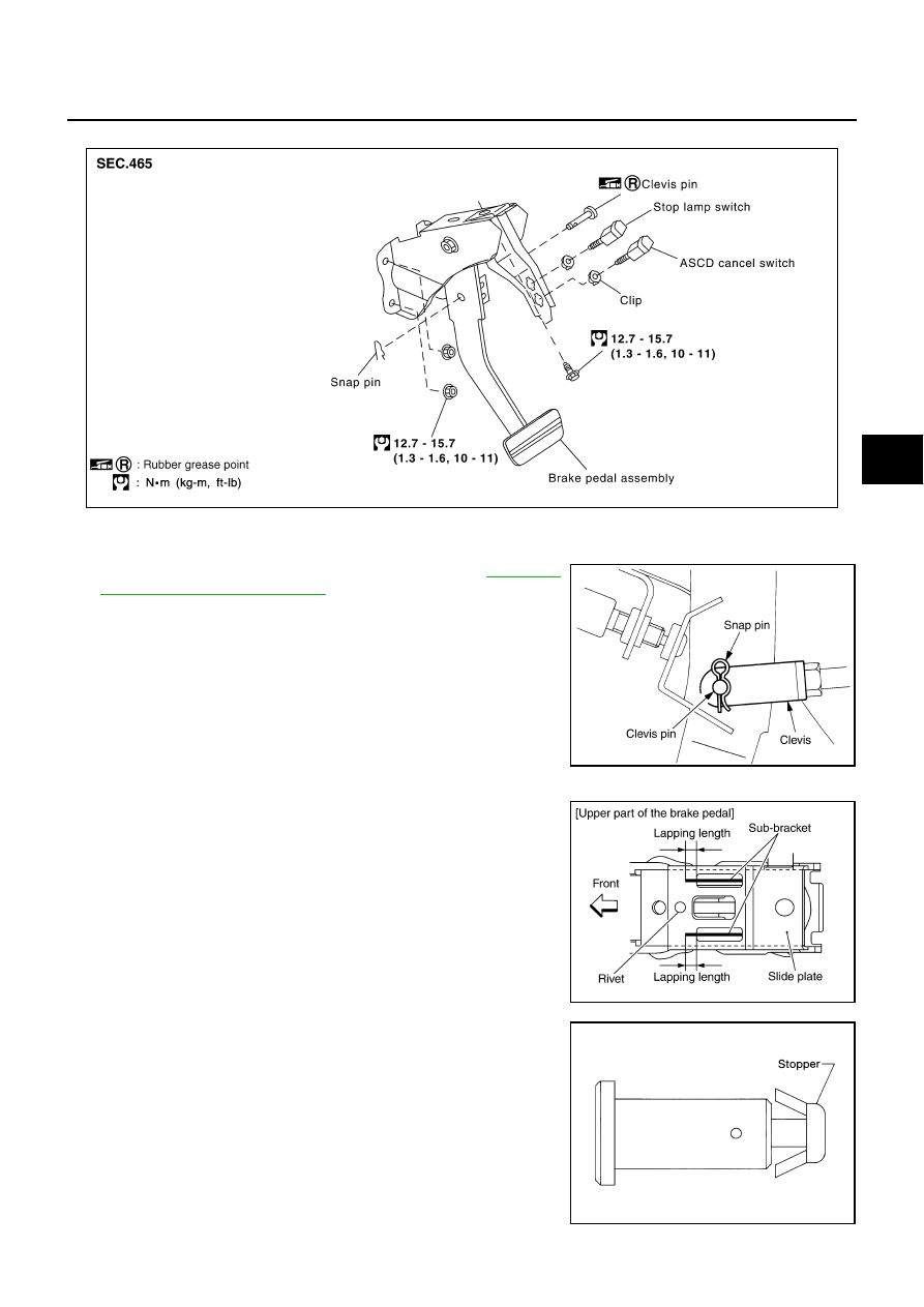
Components
NFS000I9
Removal and Installation
NFS00059
REMOVAL
1.
Remove the instrument driver lower panel. Refer to
Instrument Driver Lower Panel"
2.
Remove stop lamp switch and ASCD cancel switch from pedal
assembly.
3.
Remove snap pin and clevis pin from clevis of brake booster.
4.
Remove mounting nuts and bolt from bracket, and remove pedal
assembly from vehicle.
INSPECTION AFTER REMOVAL
●
Check brake pedal upper rivet for deformation.
●
Make sure that the lapping length of sub-bracket and slide plate
is at least 5.5 mm (0.217 in).
●
Check brake pedal for bend, damage, and cracks on the welded
parts.
●
Replace brake pedal assembly if any non-standard condition is
detected.
●
Check clevis pin and plastic stopper for damage and deforma-
tion. Replace clevis pin if there are.
SFIA1783E
SFIA0159E
SFIA2824E
SBR997