Hummer H3. Manual - part 619


  Index      Hummer     Hummer H3 - service repair manual 2006-2009 year


Search            


Content   ..  617  618  619  620   ..


Hummer H3. Manual - part 619


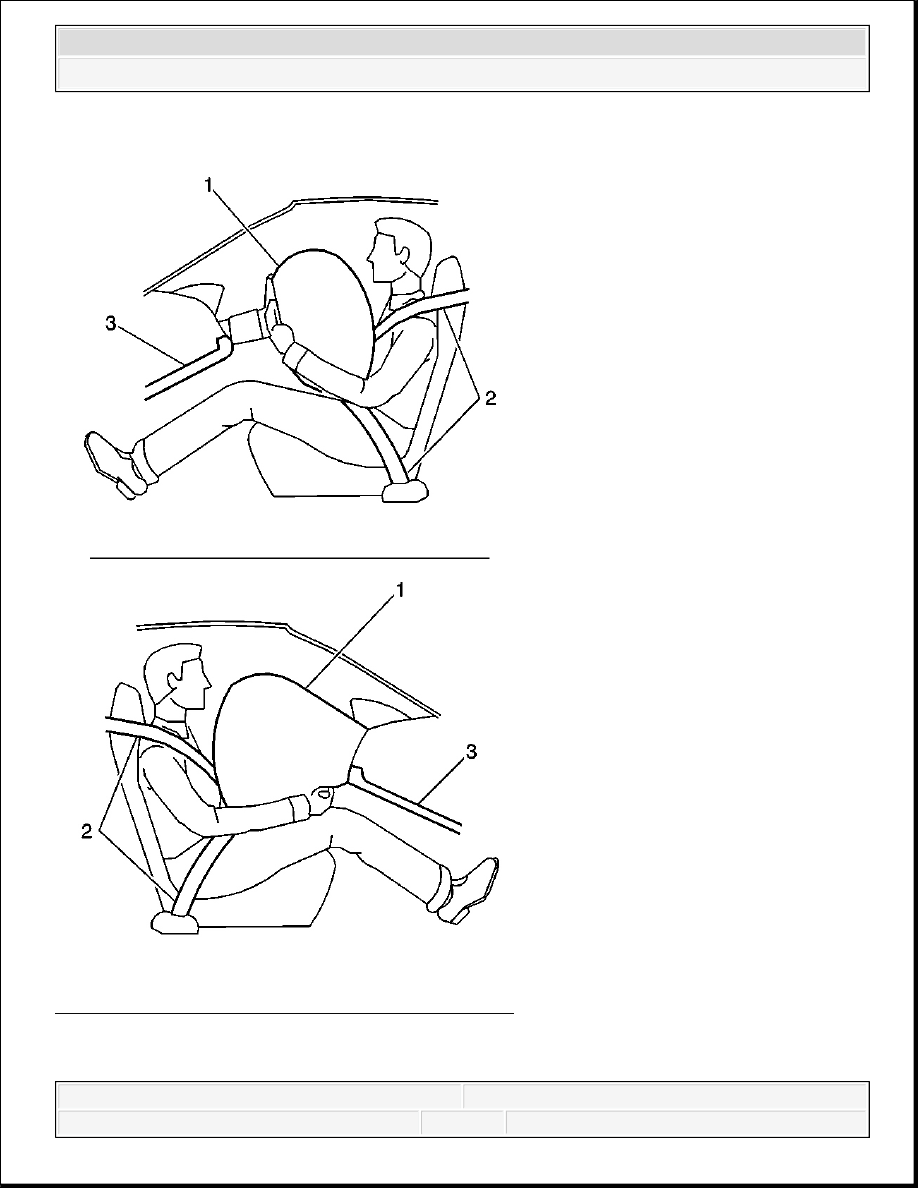
Fig. 130: Illustrating Deployed Inflatable Restraint 
Courtesy of GENERAL MOTORS CORP. 

The Supplemental Inflatable Restraint (SIR) System supplements the protection offered by the 


2007 Hummer H3 

2007 RESTRAINTS Supplemental Inflatable Restraints - H3


occupants Seat Belt System (2). The SIR system may contain several inflator modules located 
throughout the vehicle, i.e. steering wheel module (1) and instrument panel (I/P) module (1). In 
addition to inflator modules, the vehicle contains an inflatable restraint Passenger Presence 
System (PPS) that measures the weight of an occupant sitting in the front passenger seat. The PPS 
uses the weight of the occupant to determine if the I/P inflator module will be enabled or 
disabled. Each inflator module has a deployment loop that is controlled by the sensing and 
diagnostic module (SDM) mounted inside the vehicle. The SDM determines the severity of a 
collision with the assistance of various sensor inputs. When the SDM detects a collision of 
sufficient force it will process the information provided by the sensors to further support air bag 
deployment. The SDM performs continuous diagnostic monitoring of the SIR system electrical 
components. Upon detection of a circuit malfunction, the SDM will set a DTC and inform the 
driver by requesting the instrument panel cluster (IPC) to turn the AIR BAG indicator ON. The 
steering column (1) and knee bolsters (3) are designed to absorb energy and compress during 
frontal collisions in order to limit leg movement and decrease the chance of injury to the driver 
and passenger. 

Frontal SIR System Description 

The frontal Supplemental Inflatable Restraint (SIR) System consists of the following components: 


AIR BAG indicator located on the instrument panel cluster (IPC)  


Driver and passenger knee bolsters  


Inflatable restraint front end sensors (left/right)  


Inflatable restraint PASSENGER AIR BAG ON/OFF indicator located on the instrument 
panel  


Inflatable restraint Passenger Presence System (PPS)  


Inflatable restraint passenger seat belt tension sensor  


Inflatable restraint seat position sensors (SPS) (left/right)  


Inflatable restraint sensing and diagnostic module (SDM)  


Inflatable restraint steering wheel module  


Inflatable restraint steering wheel module coil  


Inflatable restraint wiring harnesses  


Seat belt pretensioners (left/right)  


Steering wheel and column  

A frontal collision of sufficient force will deploy the frontal air bags. The SDM contains a 
sensing device that converts vehicle velocity changes to an electrical signal. In the event of a 
frontal collision, the SDM receives a signal from the front end sensors which assists the SDM in 


2007 Hummer H3 

2007 RESTRAINTS Supplemental Inflatable Restraints - H3


determining the severity of some frontal collisions. The SDM contains a microprocessor that 
performs calculations using the measured accelerations. The SDM compares these calculations to 
a value stored in memory. When the generated calculations exceed the stored value, the SDM will 
cause current to flow through the frontal deployment loops deploying the frontal air bags. Once 
the air bags are inflated they quickly deflate through the air bag vent holes. After the air bags 
have deployed, the SDM sets a diagnostic trouble code (DTC) and requests the IPC to turn the 
AIR BAG indicator ON. The SDM, instrument panel (I/P) module, steering wheel module, 
steering wheel module coil and the connecting wires makeup the frontal deployment loops. The 
SDM continuously monitors the deployment loops for malfunctions and requests the IPC to turn 
the AIR BAG indicator ON if a fault is detected. 

Side SIR System Description (Front) 

The side Supplemental Inflatable Restraint (SIR) System (front) consists of the following 
components: 


AIR BAG indicator located in the instrument panel cluster (IPC)  


Inflatable restraint roof rail modules (left/right)  


Inflatable restraint sensing and diagnostic module (SDM)  


Inflatable restraint side impact sensors (SIS) (left/right)  


Inflatable restraint vehicle rollover sensor  


Inflatable restraint wiring harnesses  

The roof rail modules (front) are located in the headliner along the roof rails. The roof rail 
modules contain a housing, inflatable air bag, initiating device and a canister of gas generating 
material. The initiator is part of the roof rail module deployment loop. When a side impact of 
sufficient force occurs the SIS detects the impact and sends a signal to the SDM. The SDM 
compares the signal received from the SIS to a value stored in memory. When the generated 
signal exceeds the stored value, the SDM will cause current to flow through the side deployment 
loop deploying the roof rail air bag. The SDM, roof rail modules (front) and the connecting wires 
makeup the side deployment loops. The SDM continuously monitors the deployment loops for 
malfunctions and turns the AIR BAG indicator ON if a fault is present. Each roof rail module 
(front) is equipped with a shorting bar located on the connector of the module. The shorting bar 
shorts the roof rail module deployment loop circuitry to prevent unwanted deployment of the air 
bag when servicing the inflator module. 

Inflatable Restraint Sensing and Diagnostic Module (SDM) 

The sensing and diagnostic module (SDM) is a microprocessor and the control center for the 
Supplemental Inflatable Restraint (SIR) System. The SDM contains internal sensors along with 


2007 Hummer H3 

2007 RESTRAINTS Supplemental Inflatable Restraints - H3


several external sensors, if equipped, mounted at various locations on the vehicle. In the event of 
a collision, the SDM performs calculations using the signals received from the internal and 
external sensors. The SDM compares the results of the calculations to values stored in memory. 
When these calculations exceed the stored value, the SDM will cause current to flow through the 
appropriate deployment loops to deploy the air bags. The SDM records the SIR System status 
when a deployment occurs and requests the instrument panel cluster (IPC) to turn the AIR BAG 
indicator ON. The SDM performs continuous diagnostic monitoring of the SIR System electrical 
components and circuitry when the ignition is turned ON. If the SDM detects a malfunction, a 
DTC will be stored and the SDM will request the IPC to turn the AIR BAG indicator ON. In the 
event that ignition 1 voltage is lost during a collision, the SDM maintains a 23-volt loop reserve 
(23 VLR) for deployment of the air bags. It is important to note, when disabling the SIR System 
for servicing or rescue operations to allow the 23 VLR to dissipate, which could take up to 1 
minute. 

Inflatable Restraint Passenger Presence System (PPS) 

The PPS is used to monitor the weight of an occupant on the front outboard passenger seat and 
communicate the status to the sensing and diagnostic module (SDM) whether to enable or 
suppress the deployment of the instrument panel (I/P) module. The PPS consist of an electronic 
control module, silicone filled sensor pad, pressure sensor, seat belt tension sensor, wiring harness 
and PASSENGER AIR BAG ON/OFF indicators. The silicone filled sensor pad is located under 
the passenger seat foam cushion and is connected by a hose clamped to the pressure sensor. The 
weight of the occupant sitting in the front passenger seat is measured as a pressure change within 
the bladder by the pressure sensor. The pressure sensor sends a voltage signal to the PPS module. 
If the pressure from the occupants weight is less than a specified value, the PPS module will send 
a suppress signal to the SDM to disable the I/P module. If the pressure from the occupants weight 
is higher than a specified value, the PPS module will send an enable signal to the SDM to enable 
the I/P module. The PPS module will notify the customer of the enable/disable status by turning 
on one of the PASSENGER AIR BAG ON/OFF indicators located on the instrument panel. The 
PPS monitors itself for faults and will set flash diagnostic trouble codes (DTCs) if a fault is 
detected. The PPS will also notify the SDM of a fault and the SDM will request the instrument 
panel cluster (IPC) to turn ON the AIR BAG indicator located on the IPC. To determine what 
DTCs have been set by the PPS, the Tech 2 is used to command the SDM to request the PPS to 
flash the DTCs using the PASSENGER AIR BAG ON/OFF indicators located on the instrument 

IMPORTANT: The Passenger Presence System (PPS) is a calibrated unit. When 

replacing the assembly all parts in the service kit must remain 
together. Do not mix any of the old parts with the new parts. After 
repairing or replacing the PPS, the system must be rezeroed in 
order to function properly.


2007 Hummer H3 

2007 RESTRAINTS Supplemental Inflatable Restraints - H3


Content   ..  617  618  619  620   ..