Geely Emgrand X7. Manual part - 596


  Главная      Geely     Geely Emgrand X7 - Manual


поиск по сайту            


содержание   ..   591  592  593  594  595  596  597  ..


Geely Emgrand X7. Manual part - 596


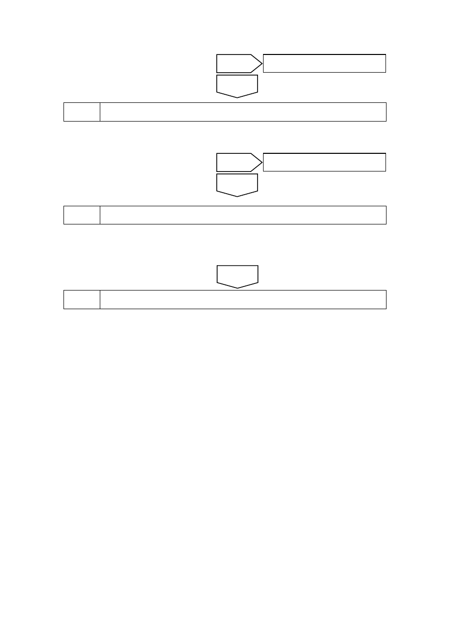
(a)  Replace fuel level sensor , refer to 2.3.8.4 fuel level sensor replacement . 

Inspect whether the fuel gauge works normally? 


(a)  Replace the combination instrument and refer to 11.6.7.1 replacement of combination 

instrument assembly. 

Confirm the completion of repair. 


The system is normal. 


Replace the fuel level sensor. 

Replace instrument cluster, 

Next 

Yes 

The system is normal. 

No 

Yes 

Go to step 8 

No 

2383


11.7.7 Diagnostic information and steps (JLD-4G2G/JLD-4G20) 

11.7.7.1 Diagnosis descriptions 

This instrument supports the OBD based on CAN buss. 

Refer to Description and Operation of Complete Vehicle Maintenance Manual to get familiar with 
the system functions and operation before starting system diagnostics, so that it will help to 
determine the correct diagnostic steps. More importantly, it will also help to determine whether 
the customer described situation is normal. 

11.7.7.2 Visual inspection 

z  Inspect installed aftermarket equipment that may affect the operation of the instrument 

system. 

z  Check the system components that is easy to access to identify whether there is significant 

damage or potential faults. 

z  Inspect whether the sensor of the instrument display information is normal. 

11.7.7.3 Definition of DTC code supported by the instrument 

DTC 

DTC description 

U100-04 

EEPROM Checksum Error 

U10018 

A/C message time-out and lost communication with A/C 

U10017 

BCM message time-out and lost communication with BCM 

U10011 

CAN network system integrity test failure 

U10010 

Detect CAN BUS off state. 


2384


11.7.7.4 Instrument terminal list 

16

1

2

3

4

5

6

7

8

9

10

11

12

13

14

15

17

32 31 30 29 28 27 26 25 24 23 22 21 20 19 18

NL11-3022b

IP01 组合仪表线束连接器


Terminal No. 

Terminal definition 

Diameter/color 

Battery power supply 

0.5R/G 

2 Ignition 

switch 

0.5Y 

3 Instrument 

panel 

0.85B 

4 Fuel 

signal 

0.35R 

Brake fluid level low (-) 

0.35P/Y 

6 Sensor 

grounding 

0.5B/O 

7 Reverse 

radar 

0.35L 

Vehicle speed input 

0.35W 

9 Parking 

brake 

(-) 

0.35P/O 

10 / 

11 

Vehicle speed output 

0.35B/R 

12 

8v power output 

0.35Br 

13 / 

14 Low 

beam(+) 

0.35O/G 

IP01 combination instrument harness connector 

2385

15 / 

16 Anti-theft 

indicator 

(-) 

0.35L/O 

17 

Subsidiary safety belt output  (-) 0.35G 

18 DISP 

button 

0.35R 

19 

Overspeed alarm off(-)(reseved  ) Reserved 

20 Can 

high 

0.5Y/G 

21 Can 

low 

0.5G/Br 

22 / 

23 

Preheating wire reserve  (-) Reserved 

24 

Oil-water seperation reserve(+) Reserved 

25 High 

beam(-) 0.35O/G 

26 High 

beam(+) 0.35O/ 

27 

Rear fog lamps(+) 0.35R/G 

28 

Front fog lamp 

0.35R/O 

29 Position 

lamp(+) 0.35L 

30 Battery 

charging 

indicator(-) 0.35R/W 

31 Low 

oil 

pressure(-) 0.35P/ 

32 Reverse 

gear 

+) 0.35G/O 

11.7.7.5 DTC U100-04 

DTC 

U100-04 

EEPROM Checksum error 

Diagnostic steps: 

Check whether the meter power supply circuit and ground circuit are normal. 


Replace instrument assembly, Refer to 11.1.7.1 replacement of Instrument cluster 
Assembly. 


Next 

Yes 

Repair the faulty part. 

No 

2386


содержание   ..   591  592  593  594  595  596  597  ..