Geely Emgrand X7. Manual part - 593


  Главная      Geely     Geely Emgrand X7 - Manual


поиск по сайту            


содержание   ..   590  591  592  593  594  ..


Geely Emgrand X7. Manual part - 593


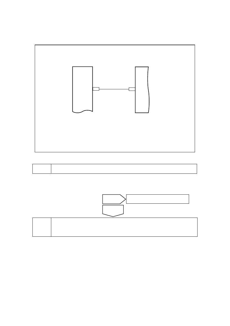
11.7.6.13 Speedometer can not indicate normally 

Circuit diagram: 

NL11-3049b

TACH

17

IP02

80

EN01

ECM

IPC

TACHO


Diagnostic steps: 

(a)  Inspect whether combined instrument wire harness connector has damage, bad connection, 

ageing and loose conditions. 

Inspect if the result is normal 


Inspect the communication between the terminal No.80 of the ECM wire harness 
connector EN01 and the terminal No.17 of the combination instrument wire harness 
connector IP02. 


1 General 

inspection 

No 

Fault discovered by maintenance 

Yes 

2371

(a)  Check resistance value between 

ECM harness connector EN01 
terminal No.80 and instrument 
cluster harness connector IP02 
terminal No.17 

Standard resistance: less than 1 Ω 

Is the resistance at a specified value? 

NL11-3050b

1

2

4

5

3

81

63

44

25

6

62

43

24 23 22 21 20 19 18 17 16 15 14 13 12 11 10

9

8

7

26

42 41 40 39 38 37 36 35 34 33 32 31 30 29 28 27

45

46

61 60 59 58

57 56 55

54 53 52 51 50 49 48 47

64

65

66

80 79 78 77 76 75 74 73 72 71 70 69 68 67

EN01 发动机控制模块线束连接器

80


NL11-3051b

16

1

2

3

4

5

6

7

8

9

10

11

12

13

14

15

17

32 31 30 29 28 27 26 25 24 23 22 21 20 19 18

IP02 组合仪表线束连接器2

17


Inspect and repair the circuit between the terminal No.80 of the ECM wire harness 
connector EN01 and the terminal No.17 of the combination instrument wire harness 
connector IP02. 

(a)  Make sure that ECU wire harness connector EN01 terminal No.80 and combined instrument 

wire harness connector IP02 terminal No.17 are connected. 

Inspect whether the speedometer works normally. 


Inspect the speed sensor. 

(a)  Check speed sensor. Refer to2.2.7.35 DTC P0335 P0336. 

Inspect whether the speedometer works normally. 

Yes 

The system is normal. 

No 

Yes 

Go to step 4 

No 

EN01 engine control module 

harness connector 

IP02 combination instrument 

harness connector2 

2372


5 Replace 

ECM 

(a)  Replace ECM and refer to 2.2.8.6 "Replacement of Engine Control Module". 

Inspect whether the speedometer works normally. 


Replace instrument cluster, 

(a)  Replace the combination instrument and refer to 11.6.7.1 Replacement of Combination 

Instrument Assembly. 

Confirm the completion of repair. 


The system is normal. 


Next 

Yes 

The system is normal. 

No 

Yes 

The system is normal. 

No 

2373


11.7.6.14 Speedometer can not indicate normally 

Circuit diagram: 

NL11-3052b

51 EN01

1

IP02

3 EN21

VSS

SPEED IN

车速传感器

2 EN21 1 EN21

ECM

IG1

IPC

IF

2

5

1

0

A


Diagnostic steps: 

1 General 

inspection 

(a)  Inspect whether combined instrument wire harness connector has damage, bad connection, 

ageing and loose conditions. 

Inspect if the result is normal 


Inspect the working condition of the vehicle speed sensor. 

(a)  For inspection of working condition of speed sensor, refer to 2.2.7.41 DTC P0502. 

Inspect whether the speedometer works normally? 


Inspect and repair the circuit between the terminal No.3 of the speed sensor wire 
harness connector EN21 and the terminal No.1 of the combination instrument wire 
harness connector IP02. 


Yes 

Go to step 4 

No 

No 

Fault discovered by maintenance 

Yes 

Body sensor 

2374


содержание   ..   590  591  592  593  594  ..