Geely Emgrand X7. Manual part - 471


  Главная      Geely     Geely Emgrand X7 - Manual


поиск по сайту            


содержание   ..  469  470  471  472  ..


Geely Emgrand X7. Manual part - 471


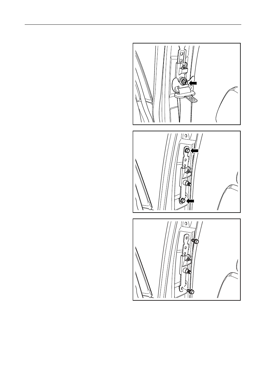
9.3.7.10 Replacement of Front Seat Belt Height Regulator 

Dismantlement Procedure 

1. 

 For dismantling of middle column upper 

trimming plate, refer to 12.9.1.3 Replacement of 
middle column trimming plate. 

2.    Remove the top fixing nut on the center pillar for 

the front seat belt. 


NL09-0049b

3.    Dismantle fixing bolt of safety belt height adjuster 

of front row seat. 


NL09-0062b

Installation Procedure: 

1.   Install front row seat safety belt height adjuster 

and tighten fixing bolt. 

Torque: 35Nm (Metric) 25. 9lb-ft(English system) 

NL09-0063b


1883


2.   Install and tighten upper fixing nut of middle 

column of front seat safety belt. 

Torque: 45Nm (Metric) 33. 3lb-ft(English system) 

3.  Install the middle column upper trimming plate. 


NL09-0051b


1884

10.1 Warning and precaution ............................ 1886 

10.1.1 Warning and precaution ............................. 1886 

10.2 Computer and integration system(JL4G18-E)
 .............................................................................. 1887 

10.2.1 Specifications ............................................. 1887 

10.2.1.1 Fastener specifications. ........................... 1887 

10.2.2 Description and Operation ......................... 1887 

10.2.2.1 Description and operation.. ..................... 1887 

10.2.3 Part position ............................................... 1889   

10.2.3.1 BCM location plan. ................................. 1889 

10.2.4 Diagnostic information and steps .............. 1890   

10.2.4.1 BCM Terminal List. ................................ 1890 

10.2.4.2 Fault diagnostic code (DTC) table .......... 1894   

10.2.4.3 DTC B1201 B1202 ................................. 1896   

10.2.4.4 DTC B1203 B1204 ................................. 1900 

10.2.4.5 DTC B1205 B1206. ................................ 1903 

10.2.4.6 DTC B1207 B1208. ................................ 1907 

10.2.4.7 DTC B1209 B1210. ................................ 1911   

10.2.4.8 DTC B1211 ............................................. 1915 

10.2.4.9 DTC B1212 ............................................. 1919   

10.2.4.10 DTC B1216. ......................................... .1921   

10.2.4.11 DTC B1237. .......................................... 1923   

10.2.4.12 DTC B1213. .......................................... 1926 

10.2.4.13 DTC B1214. .......................................... 1928 

10.2.4.14 DTC B1215. .......................................... 1930 

10.2.4.15 DTC B1217. .......................................... 1932   

10.2.4.16 DTC B1218. .......................................... 1935 

10.2.4.17 DTC B1220. .......................................... 1938   

10.2.4.18 DTC B1222 .......................................... 1941 

10.2.4.19 DTC B1224 .......................................... 1944 

10.2.4.20 DTC B1236   ........................................ 1945 

10.2.4.21 DTC U1000 .......................................... 1947   

10.2.4.22 DTC U1004 .......................................... 1949   

10.2.4.23 DTC U1005 ......................................... .1951   

10.2.5 Dismantle and install ................................. 1953   

10.2.5.1 BCM replacement. .................................. 1953   

10.3 Computer integrated manufacturing 
system(JLD-4G20/JLD-4G24) ........................... 1954   

10.3.1 Specification .............................................. 1954 

10.3.1.1 Fastener specifications ........................... 1954 

10.3.2 Description and operation ......................... 1955   

10.3.2.1 Description and operation....................... 1955 

10.3.3 Diagnostic information and steps .............. 1963 

10.3.3.1 BCM Terminal List. ............................... 1963   

10.3.3.2 Fault Diagnosis Code (DTC) List. ......... .1970   

10.3.3.3 DTC B1201 B1202. ................................ 1972 

10.3.3.4 DTC B11B312. B11B312. ..................... 1978 

10.3.3.5 DTC B11B312. B11B312 ...................... 1983 

10.3.3.6 DTC B11B512. B11B512 ...................... 1986 

10.3.3.7 DTC B11D214. B11D213. B11D212. 
B11D312. B11D313. B11D314. .......................... 1989 

10.3.3.8 U012187. U010087. U015187. U12501C. 
U12511C. U015587 ............................................. 1992   

10.3.5 Dismantle and install ................................. 1993 

10.3.5.1 BCM replacement ................................... 1993 

10.4 Programming and Setting. ............................ 1994 

10.4.1 Programming and Setting. ......................... 1994 


10.1 Warning and precaution 

10.1.1 Warning and precaution 

Warning on Battery Disconnection 

Warning! 

Unless directed, otherwise, the ignition and start switch must be in OFF or LOCK position, and all electrical loads 
must be OFF before servicing any electrical component. Disconnect the negative battery cable if a tool or any 
equipment easily comes in contact with an exposed electrical terminal. Failure to follow these precautions may 
result in personal injury and/or damage to the vehicle or its components. 

Road Test Warning 

Warning! 

Test a vehicle on the roads under safe conditions and obey all traffic laws. Do not attempt any operation that could 
jeopardize vehicle control. Failure to obey these precautions will lead to serious personal injury and vehicle 
damage. 

Window Quick Down Warning 

Warning! 

Operate the power window switch when working inside the driver door. When operated, the Quick Up/Down 
function allows the window to move very quickly without stopping, which could cause personal injury. 

Ignition OFF When Disconnecting Battery Notice 

Notes: 

Always turn the ignition OFF when connecting or disconnecting battery cables, battery chargers or jumper cables. 
Failing to do so may damage the control module or other electronic components. 

Precautions on Power System Control Module and Electrostatic Discharge 

Notes: 

Do not touch the connector pins or soldered components on the circuit board in order to prevent possible 
electrostatic discharge (ESD) damage to the ECM. 


1886


содержание   ..  469  470  471  472  ..