Geely Emgrand X7. Manual part - 397


  Главная      Geely     Geely Emgrand X7 - Manual


поиск по сайту            


содержание   ..   394  395  396  397  398  ..


Geely Emgrand X7. Manual part - 397


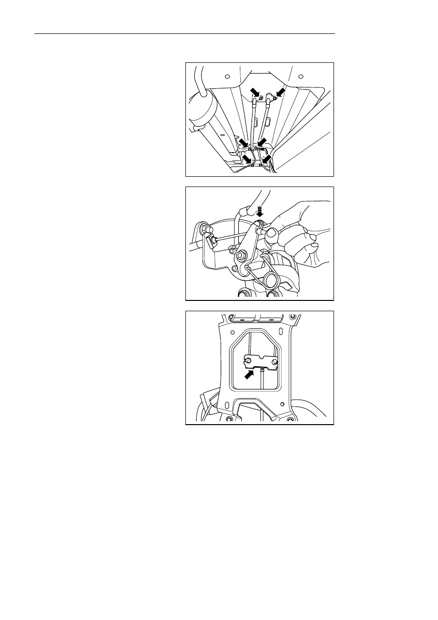
Installation procedure: 

1.    Install left/ right rear parking brake cable . 

2.   Install rear parking brake cable fixing bolt and 

spring clip. 

Torque:9Nm (Metric) 6.6 lb-ft (English system) 

NL06-0064b


3.  Respectively install left and right rear parking 

brake cables onto rear brake caliper. 

NL06-0065b


4.   Lower the vehicle. 

5.    Engage the left and right parking brake cable into 

the cable balance collar. 

NL06-0061b


1587


6.  Install parking brake operation mechanical 

assembly cable, and press mounting piece to 
make it clip parking brake operation mechanical 
assembly cable. 

NL06-0066b


7.  Install the parking brake control mechanism 

assembly control cable adjustment nut. 

Torque:9 Nm (Metric) 6.7 lb-ft (English system) 

NL06-0059b


8.  Adjust the parking brake control mechanism 

assembly control cable according to the length of 
the thread from the top of the control cable to the 
hexagon nut which is measured and recorded. 

9.  If necessary, adjust the parking brake control 

mechanism assembly. See 6.5.5.4 Adjustment of 
Parking Brake Control Mechanism Assembly. 

10.  Pull up the parking brake control mechanism 

assembly. 

11.    Install the auxiliary instrument panel. 

12 .  Connect the battery negative cable.   

NL06-0054b


1588


6.5.5.4 parking brake control mechanism assembly adjustment 

Adjust process 

Warning! 

See Warnings For vehicle lifting in Warnings and 
precaution. 

1.  Release parking brake operation mechanism 

assembly. 

2.    For lifting vehicle, refer to 1.3 lifting vehicle. 

3. 

 Inspect whether parking brake operation 

mechanical assembly cable can move freely. 

NL06-0067b


4.   Lower the vehicle. 

5.   For dismantling of auxiliary instrument panel, 

refer to Replacement of auxiliary instrument 
panel. 

6.   Slightly lift the vehicle to enable the wheels to 

rotate freely. 

7.   Tighten the parking brake control mechanism 

assembly cable adjustment nut until the wheel 
can hardly rotate. 

8.   Loosen the nut until the rear wheel can freely 

rotate. 

9.   Lower the vehicle. 

10.  Pull up parking brake. install auxiliary instrument 

panel 

NL06-0068b


1589


6.6 ABS/TCS/EBD/ESP 

6.6.1 Specifications 

6.6.1.1 Fastener specifications 

Torque Range 

Fastener Name 

Model 

Metric (N.m) 

English system 

(lb-ft) 

Fixed wheel speed sensor bracket nut 

M6 

8-10 

5.9-7.4 

Fixed wheel speed sensor support bolt   

M6×18 

16-20 

11.8-14.8 

A fixed HECU controller assembly 

Six fixed braking hoses 

M8×20 15-21 

11.1-15.5 

6. 6. 1. 2 Speed sensor technique specifications 

Wheel speed sensor 

Descriptions 

Sensor type 

Hall-type Speed Sensor 

Operating voltage 

12±0.1V 

Signal Current 

Low level: 5.6 - 8.4 mA; high level: 11.2 - 16.8 mA 

Clearance value with signal panel 

Front axle 1.626 mm (0.06 in) rear axle 0.597 mm (0.02 in) 

1590


содержание   ..   394  395  396  397  398  ..