Geely Emgrand X7. Manual part - 391


  Главная      Geely     Geely Emgrand X7 - Manual


поиск по сайту            


содержание   ..  389  390  391  392  ..


Geely Emgrand X7. Manual part - 391


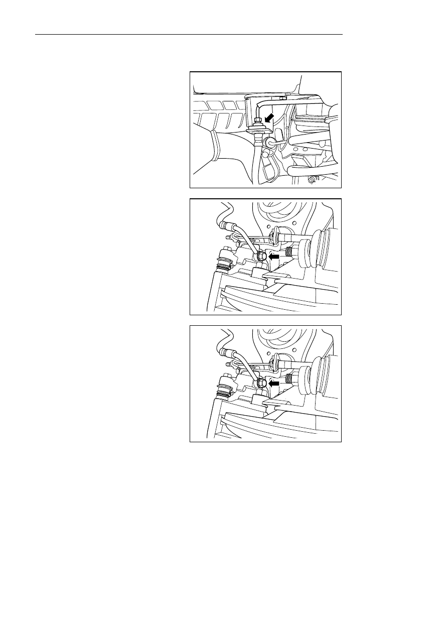
6.4.5.4 Brake hose replacement (rear) 

Dismantle procedure 

Notes: 

See Important precaution for brake fluid affected paint 
and electrical parts in warnings and precaution. 

1.   Discharge brake fluid 

2.    For lifting vehicle see 1.3 Lifting vehicle. 

3.   For dismantling of rear wheel, refer to 4.4.5.1 

Replacement of wheels. 

NL06-0037b


4.   Dismantle connecting bolt between brake hose 

and brake hard pipe, and pull out spring stop 
piece, and then remove brake hose from fixing 
frame. 

5.   Remove the bolt and detach the flexible brake 

hose from the rear brake cylinder. 

6.    Dismantle the rear flexible brake hose. 


NL06-0038b


Installation procedure: 

Warning! 

See Warning for replacement of Brake Pipe in 
Warnings and precaution. 

1.    Install brake hose to rear brake slave pump, and 

fixed bolt. 

Torque: 19Nm (Metric) 14 lb-ft (English system) 

NL06-0038b


1563


2.    Connect the brake host and brake hard tube and 

fasten the bolt to block into the spring stop plate. 

3.   Install the wheel. 

Notes: 

See Important precaution for filling brake system with 
brake fluid in warnings and precaution . 

4.    Fill with braking fluid. 

5.   Check leakage. 

Notes: 

The method of dismantling the rear brake left and 
right brake hoses is similar. 

NL06-0037b


1564


6.4.5.5 Hydraulic brake system exhaust process 

Notes: 

See Important precaution for filling brake system with brake fluid in warnings and precaution . 

Notes: 

The air in the hydraulic brake adjustor cannot be discharged manually. If the air is mixed into the ABS hydraulic 
brake adjustor or the ABS hydraulic brake adjustor without being full of oil is installed, the fault diagnostic unit 
needs to be used for discharging the air in the brake system. Before the vehicle leaves the factory, the ABS 
Hydraulic brake regulator is fully filled with fluid and de-aerated, air will not enter the ABS hydraulic brake 
regulator during the normal maintenance procedures involving the regulator. In this case, use manual de-aeration 
procedures. 

Notes: 

If making no question of entering into the master cylinder, start the execution of the exhaust procedure from step 5. 
If suspecting that air enters the master pump, start the air emission in the master cylinder from the step 2. 

Notes: 

See Important precaution for brake fluid affected paint 
and electrical parts in Warnings and precaution. 

1.   Keep engine on flameout condition, step brake 

pedal for several times unti pressure in booster is 
released completely. 

2.   Fill brake fluid into main pump fluid reservoir, 

and fluid level in main pump fluid reservoir 
during exhaust operation should keep at least 
more than a half. 

3.  Slowly press down brake pedal and keeping . 

NL06-0039b


4.   Release one brake line on the clutch master 

cylinder and tighten the brake oil pipe connector 
when the brake fluid flows out from the port. 

Torque: 16Nm (Metric) 11. 8lb-ft (English system) 

5.  Loosen the other brake line on the master 

cylinder and tighten the brake line joint when the 
brake fluid flows out from the port. 

Torque: 16Nm (Metric) 11.8 lb-ft (English system) 

NL06-0040b


1565


6.   Repeated operation of steps 2-5 at third time to 

fourth time. 

7.  Dismantle the bleed screw dust cover and 

connect one transparent pipe to the rear bleed 
screw on the rear right brake caliper to immerse 
the pipe into the brake fluid in the transparent 
container. exhaust the air in the rear right brake 
caliper following the procedures below. 

NL06-0041b


8.  Depress and hold the brake pedal slowly rather 

than suddenly. 


NL06-0042b


9.   Loosen the bleed screw while depressing the 

brake pedal to exhaust the air in the brake caliper. 

10.  After air bule escape into brake fluid container, 

slightly tighten rear air draining screw. 

11.   Slowly loosen brake pedal. 

12.  Repeat step 6-9.until exhaust all air 

13.  When loosening bleed screw, if the container no 

longer appears air bubbles, it indicates that air is 
drained out completely. 

Notes: 

In the exhaust process, the master cylinder reservoir 
liquid level should be maintained more than half. 

14. Tighten bleed screw. 

Torque: 6 . 5Nm (Metric) 4. 8lb-ft (English system) 

NL06-0041b


1566


содержание   ..  389  390  391  392  ..