Geely Emgrand X7. Manual part - 357


  Главная      Geely     Geely Emgrand X7 - Manual


поиск по сайту            


содержание   ..   354  355  356  357  358  ..


Geely Emgrand X7. Manual part - 357


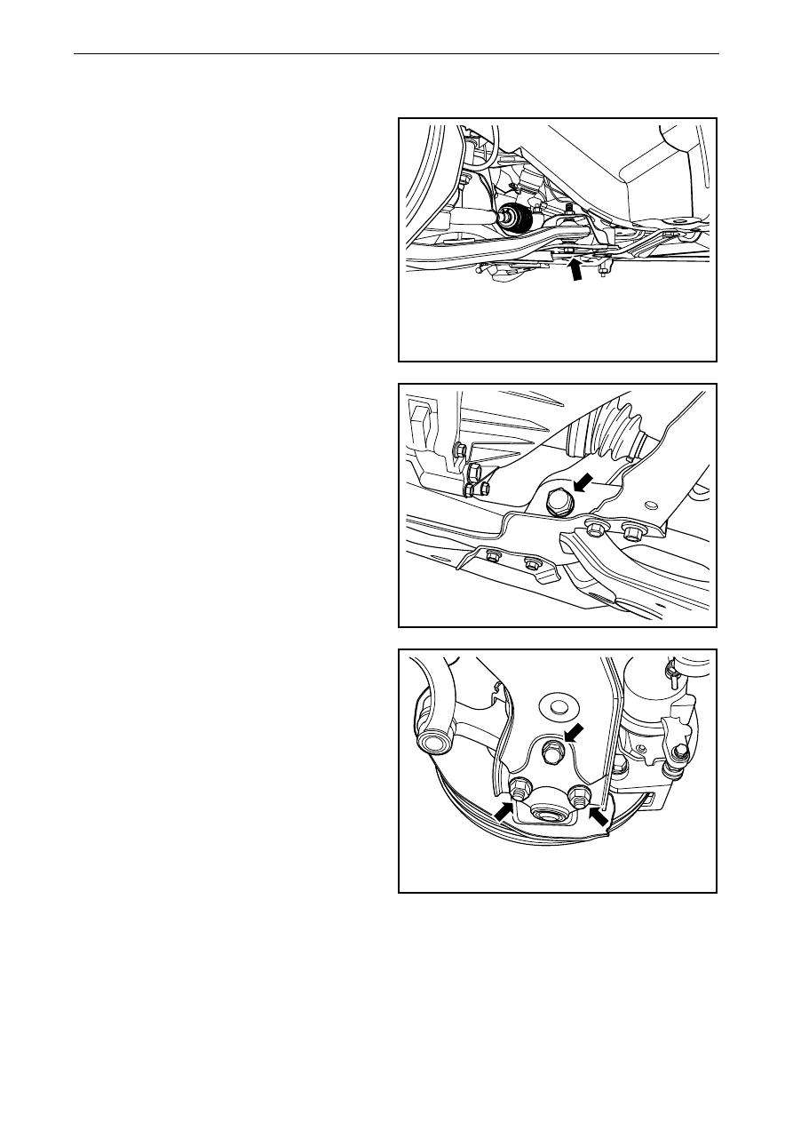
Installation Procedure: 

Notes: 

See Important precaution for fastener in warnings and 
precautions. 

1. 

Install swing arm onto front auxiliary frame. 

2.  Install and tighten through bolt of lower swing 

arm and front auxiliary frame. 

Torque:180 Nm (Metric) 133 lb-ft (English system) 

NL04-0003b

3.  Install connecting bolt on the front of lower 

swing arm and front auxiliary frame. 

Notes: 

You must tighten the bolt to the specified torque after 
placing down the wheel. 

Torque:180 Nm(Metric) 133 lb-ft(English system) 

NL04-0002b

4.  Install fixing bolt and nut between lower swing 

arm and lower swing arm ball head. 

Torque:145 Nm(Metric) 107.3 lb-ft(English system) 

5. 

Install the wheel. 

6. Lower 

the 

vehicle. 


NL04-0001b


1427


4.2.7.2 Lower swing arm bushing replacement 

Dismantle procedure 

Notes: 

Only one replacement of the bushing block is allowed.
 

In case of the second bushing block abnormality; 

you have to replace the lower swing arm assembly. 

1.  For dismantling of lower swing arm ball head, 

refer to 4.2.7.7 replacement of lower swing arm 
ball head assembly. 

2.  For dismantling of lower swing arm assembly, 

refer to 4.2.7.1 replacement of lower swing arm 
assembly. 

NL04-0004b

3.  Use dismantling tool of bushing to dismantle 

front bushing of lowe swing arm. 

NL04-0005b

4. 

Remove the swing arm rear bushing with bushing 
dismantlement tool. 

NL04-0006b


1428


Installation procedure: 

1. Apply 

multi-purpose 

grease 

to rear shaft of lower 

swing arm, and put rear sleeve into rear shaft of 
lower swing arm. 

NL04-0007b

2.  Apply multi-purpose lubricating grease on front 

shaft of lower swing arm, and press lower swing 
arm front bushing into front shaft of lower swing 
arm. 

3. 

Install lower swing arm assembly. 

4. 

Install lower swing arm ball head. 


NL04-0008b


1429


4.2.7.3 Front post assembly replacement 

Dismantle procedure: 

1   Lifting vehicle 

2.  For dismantling of front wheels, refer to 4.4.5.1 

replacement of wheels. 

3.  Dismantle connecting nut 1 between front 

stabilizer connecting rod and front shock 
absorber, and loose stabilizer rod from shock 
absorber. 

4. 

Dismantle bolt 2 of fixing support of front brake 
oil pipe. 

5. 

Detach the brake oil pipe and wheel speed sensor 
from the shock absorber. 

6.  Remove connecting bolt 3 between the knuckle 

and front shock absorber. 

7.  Remove 3 fixing nuts on the top of the front 

shock absorber. 

8. 

Dismantle the front post assembly from the wheel 
casing side. 


1

3

3

2

NL04-0009b

NL04-0010b

Installation procedure: 

1. 

Install front shock absorber assembly, and tighten 
upper 3 fixing nuts. 

Notes: 

Be sure to operate carefully in order to avoid 
damaging or scratching the coating when moving the 
coiling spring  of the suspension. Early failure may 
be caused by coating damage. 

See Important precaution for fastener in warnings and 
precautions. 

Torque:50 Nm(Metric) 37 lb-ft(English system) 


NL04-0011b

1430


содержание   ..   354  355  356  357  358  ..