Geely Emgrand X7. Manual part - 258


  Главная      Geely     Geely Emgrand X7 - Manual


поиск по сайту            


содержание   ..   254  255  256  257  258  259 ..


Geely Emgrand X7. Manual part - 258


10.  Use wooden handle to push out 

cylinder 4 piston connecting rod 
assemblies, and mark the position 
of cylinder 4 on piston and 
connecting rod assemblies. 

FE02-0227b

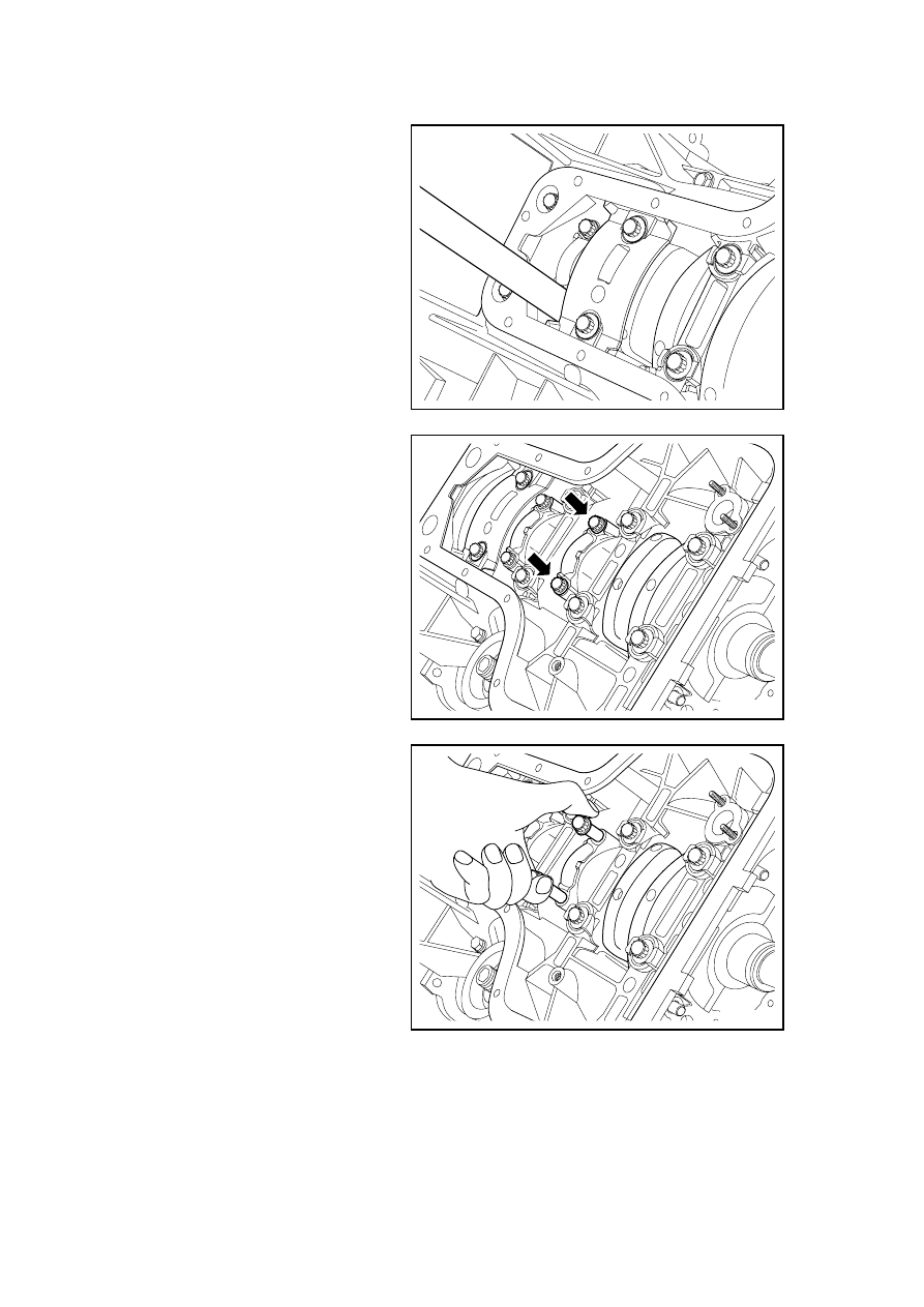
11.  Rotate crankshaft to180?, make 

2-3 cylinders on lower stop point 
position, and then dismantle bolt 
of connecting rod bearing cover 
of cylinder 2. 

FE02-0228b

12. Hold the connecting rod bolts 

and take out the Cylinder 2 
connecting rode bearing cap and 
mark the Cylinder 2 position on 
the bearing cap. 

FE02-0229b

1031

13.  Use wooden handle to push out 

piston connecting rod 
components of cylinder 2, and 
mark the position of cylinder 2 
on piston and connecting rod 
components. 

FE02-0230b

14. Remove the bolt for the #3 

cylinder connecting rod bearing 
cover. 

FE02-0231b

15. Hold the connecting rod bolts 

and take out the Cylinder 3 
connecting rode bearing cap and 
mark the Cylinder 3 position on 
the bearing cap. 

FE02-0232b

1032

16.  Use wooden handle to push out 

piston connecting rod 
components of cylinder 3, and 
mark the position of cylinder 3 
on piston and connecting rod 
components. 

FE02-0233b

Carry out the following inspection 
procedures prior to the installation 
of the piston. 

1.  Inspect whether the rod is bent or 

distorted. If the rod is bent or 
distorted, replace the connecting 
rod. 

Cross degree: 0.03/100 (metric) 
0.001/3.9 (Inch) 

Twisted Degree: 0.05/100 (Metric) 
0.002/3.9 (English system) 

2. Inspect the connecting rod 

bearings. 

3.  Inspect whether the bottom rod is 

worn. 

4.  Inspect whether the connecting 

rod upper end is scratched. 

5.  Inspect whether there is the 

crankshaft connecting rod 
bearing journal wear and tear. 

6.  Inspect whether the piston is 

scratched, cracked and worn. 

7.  Inspect the piston and piston pin 

mating. 

Standard value: 0 . 005-(-0 . 
001mm)(Metric) 

0.0002-(-0.00004in)(English system) 

FE02-0234b

1033

8.  Inspect piston pin and connecting 

rod clearance. 

Standard value :0 . 005 ~ 0 . 
011mm(Metric) 

0.00020.0004in (English system) 

9. Check the fitting clearance 

between the piston pin and piston 
pin hole. 

Standard Value 

(-0.001)-0.005 mm (Metric) 
(-0.00003)-0.0002 in (English 
system) 

10.  Inspect whether the engine block 

cylinder bore is worn, runout and 
taper. 

11.  Inspect whether the engine block 

cylinder bore is polished, if 
necessary, slightly polish the 
cylinder bore. 

FE02-0235b

12.  With a ruler and gap regulator, 

inspect the engine block top 
surface flatness. 

Standard value :0 . 05mm(Metric) 
0 . 002in(English system) 

13.  Select a new set of piston rings, 

use a gap regulator to measure 
piston ring end gap. 

Oil ring end gap:0,20

0,70mm(Metric)/0,0079

0,0276in(English system) 

The second compression ring end gap: 
0.40-0.55mm (Metric)/ 
0.0157-0.0217in (English system) 

The first compression ring end gap: 
0.25-0.35mm 
(Metric)/0.0098-0.0138in (English 
system) 

14. Inspect the connecting rod 

bearings gap. 

Standard velue : 0.020 ~ 0.044 
mm(Metric)/0.0007 ~ 0.0017 in

English system) 

15. Inspect the connecting rod 

bearing clearance. 

FE02-0236b

1034


содержание   ..   254  255  256  257  258  259 ..