Geely Emgrand X7. Manual part - 28


  Главная      Geely     Geely Emgrand X7 - Manual


поиск по сайту            


содержание   ..  20  21  22  23  24  25  26  27  28  29  ..


Geely Emgrand X7. Manual part - 28


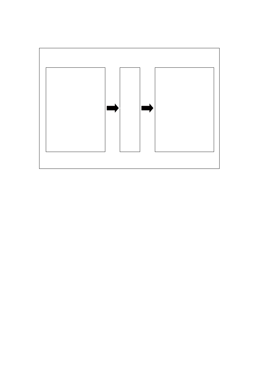
2.2.6 Electrical schematic diagram 

2.2.6.1 Electrical schematic diagram 


1. 12V 蓄电池电源
2. 12V 点火开关电源
3. 12V 电源接地
4. 5V 传感器电源接地
5. 点火模块驱动接地
6. 进气歧管压力温度传感器
7. 加速踏板位置传感器
8. 节气门位置传感器
9. 冷却液温度传感器
10.前氧传感器
11.后氧传感器
12.曲轴位置传感器
13.爆震传感器
14.车速传感器
15.空调请求信号
16.空调压力信号
17.制动信号

1. 5V 传感器参考电源
2. 点火线圈控制
3. 喷油嘴控制
4. 电子节气门电机控制
5. 油泵继电器控制
6. 碳罐电磁阀控制
7. 机油控制阀控制
8. 空调离合器继电器控制
9. 低速散热风扇继电器控制
10.高速散热风扇继电器控制
11.前氧传感器加热控制
12.后氧传感器加热控制
13.CAN总线
14.串行数据线

NL02-0028c

1. 12V battery power supply   
2. 12Vignition switch power supply   
3. 12V power grounding   
4. 5V sensor powergrounding   
5. Drive grounding of ignition module 
6. Air intake manifold pressure 
temperature sensor 
7. Accelerator pedal position sensor 
8 .Throttle position sensor   
9 .Coolant temperature sensor 
10 .Front oxygen sensor   
11 .Rear oxygen sensor   
12 .Crankshaft position sensor   
13 .Knock sensor   
14 .Speed sensor   
15 .Air conditioning request signal 
16 .Air conditioning pressure signal   
17 .Brake signal 

Engi

ne

 co

ntr

ol u

nit 

1. 5Vsensor reference powersupply 
2 .Ignition coil control   
3 .Injecting nozzle control   
4 .Electric throttle motor control   
5 .Fuel pump relay control   
6 .Canister electromagnetic valve control 
7 .Oil control valve control   
8 .Air conditioning clutch relay control   
9 .Low speed radiator fan relay control   
10 .High speed radiator fan relay control   
11 .Front oxygen sensor heating control   
12 .Rear oxygen sensor heating control   
13 .CAN main wire   
14 .Serial data lines 

111

2.2.7 Diagnostic information and procedures 

2.2.7.1 Diagnosis descriptions 

Before carrying out the control system diagnostic, refer to “2.2.2 Description and Operation” and 
“2.2.3 System Operating Principle”. Understand and get familiar with control system operating 
principle, and then start systematic diagnostic, so that it will help to determine the correct 
diagnostic steps. More importantly, it will also help to determine whether the situation described 
by the customer is normal. 

Any control system fault diagnosis should start with Control System Inspection. Control System 
Inspection will guide the service personnel to take the next logical step to diagnose the fault. 
Understand and correctly use the diagnostic flow chart can reduce the diagnostic time and avoid 
misjudge on components. 

2.2.7.2 Inspection of control system 2.2.7.6 Definition of type of fault diagnosis code 

Before inspecting the control system, please do the following primary inspections: 

1.  Inspect the battery terminal voltage to ensure an adequate power supply and a stable voltage. 

2.  Inspect the battery cables, clean and tighten. 

3.  Inspect the system components easy to access or visible to determine whether there are 

obvious damages that may cause the symptoms, such as the damage to the vacuum tube and 
the connection reliability of wiring harness connectors. 

4.  Inspect whether the control module and battery main ground points are normal and whether 

the copper plates at the ground points have oxidation, loose or other signs. 

5.  Check whether the control system is equipped with after-sales additional devices which may 

influence its normal operation. 

z  Control System Inspection Process 

2.2.7.3 Intermittent fault inspection 

Notes: 

1. Clear 

DTC 


2.  Carry out simulation tests. 

3.  Inspect and shake the harnesses, connectors and terminals. 

When DTC inspection can not identify the fault, the fault occurs only occasionally in use. At this 
point you should confirm all circuits and components that can possibly lead to the fault. In many 
cases, carrying out the basic inspections shown in the following flow chart can quickly and 
efficiently identify the fault position, especially for harness connector poor contact and other 
faults. 

Fault Definition: the fault currently does not appear, but the historical record indicates that the 
fault has appeared before. Or the customer reported the fault, but as the fault is not relevant to the 
DTC, the fault symptoms do not appear at present. 

Is the battery voltage normal? 

Notes: Turn the ignition switch to OFF position. 

Results Intake 

11 V or higher 

Yes 

Less than 11V 

No 

112


Inspect visually and physically 

This step is an important method to initially identify the fault location before the area detection: 

A.  Inspect harness for damage, wear and tear. 

B.  Inspect whether the harness is routed properly. Do not place harness near a device with high 

voltage or high current running through: 

C.  Start motor, generator and other motor components. When these components are working, 

they will introduce great electromagnetic interference, thus affecting the proper signal 
transmission, resulting in system can not work properly. 

D.  Ignition coil, ignition conductor, etc. 

E.  Inspect a vacuum hose for cracking, damage or distortion. Confirm the pipeline’s correct 

connection and routing. 

F.  Inspect whether there is air intake system leakage. For example, the throttle body installation 

surface, idle speed control valve, intake manifold sealing surface and so on. 

G.  Inspect the engine control module (ECM) ground point and the body ground for oxidation, 

loose, incorrect position, etc. The control system ground point can not be changed at will, as 
this will affect the proper operation of the control system. 

H.  Inspect whether the battery positive and negative cable connections are reliable, whether 

there is loose, oxidation, and corrosion and so on. 


Inspect the wiring harness and connector. 

A.  Many intermittent faults are caused by vibration, distortion, uneven roads, and improper 

operation of components or connectors dislocation. 

B.  If the circuit resistance is too high, it may result in components can not work properly. Use a 

fault diagnosis tester to drive the actuators, if not working, inspect whether the resistance in 
the circuit is too high or other wire faults. 


Reproduce the fault and use instruments to record engine control module data. 

A.  Connect a fault diagnosis tester and use the data record function to record road test data 

during the occurrence of the intermittent fault. After pressing the vehicle data recorder button, 
the scan tool can record engine control module data when intermittent fault occurs, and then 
the data can be used to identify the fault location. 

B.  Another diagnostic method is when the vehicle is driven connect a digital multimeter to the 

suspicious circuit. Digital multimeter abnormal readings may indicate the fault location. 


Fault indicator gives intermittent light, but a DTC is not set in the system. 

Next 

Next 

Next 

No 

Inspect the battery. 

Yes 

113

The following conditions may cause intermittent fault indicator light, but the system does not set 
the DTC: 

A.  Electromagnetic interferences are caused by relay, solenoid valve or switch controlled by 

ECM, which work abnormally. 

B.  Non-original or after-sale accessories, such as phone, alarm, lamp or radio equipment, are not 

installed properly. 

C.  Intermittent fault indicator light control circuit short to ground. 

D.  Engine control module ground point is loose. 


6 Other 

inspections 

A.  Test whether Air-Conditioning compressor clutch diodes at both ends and other diodes are in 

open circuit. 

B.  Inspect whether there are following conditions existing in charging system: 

z  Generator rectifier fault within the electrical system may result in the alternating current 

signal interference. 

z  Generator output voltage is correct or not. If the generator output voltage is lower than 9V or 

higher than 18V, repair the charging system. 


Enter Fault Symptom Table 

Next 

Next 

114


содержание   ..  20  21  22  23  24  25  26  27  28  29  ..