Freightliner Coronado 132 / 122SD. Manual - part 21
 

  Index      Freightliner     Freightliner Coronado 132, Freightliner 122SD - service repair manual


Search            


Content   ..  19  20  21  22   ..


Freightliner Coronado 132 / 122SD. Manual - part 21


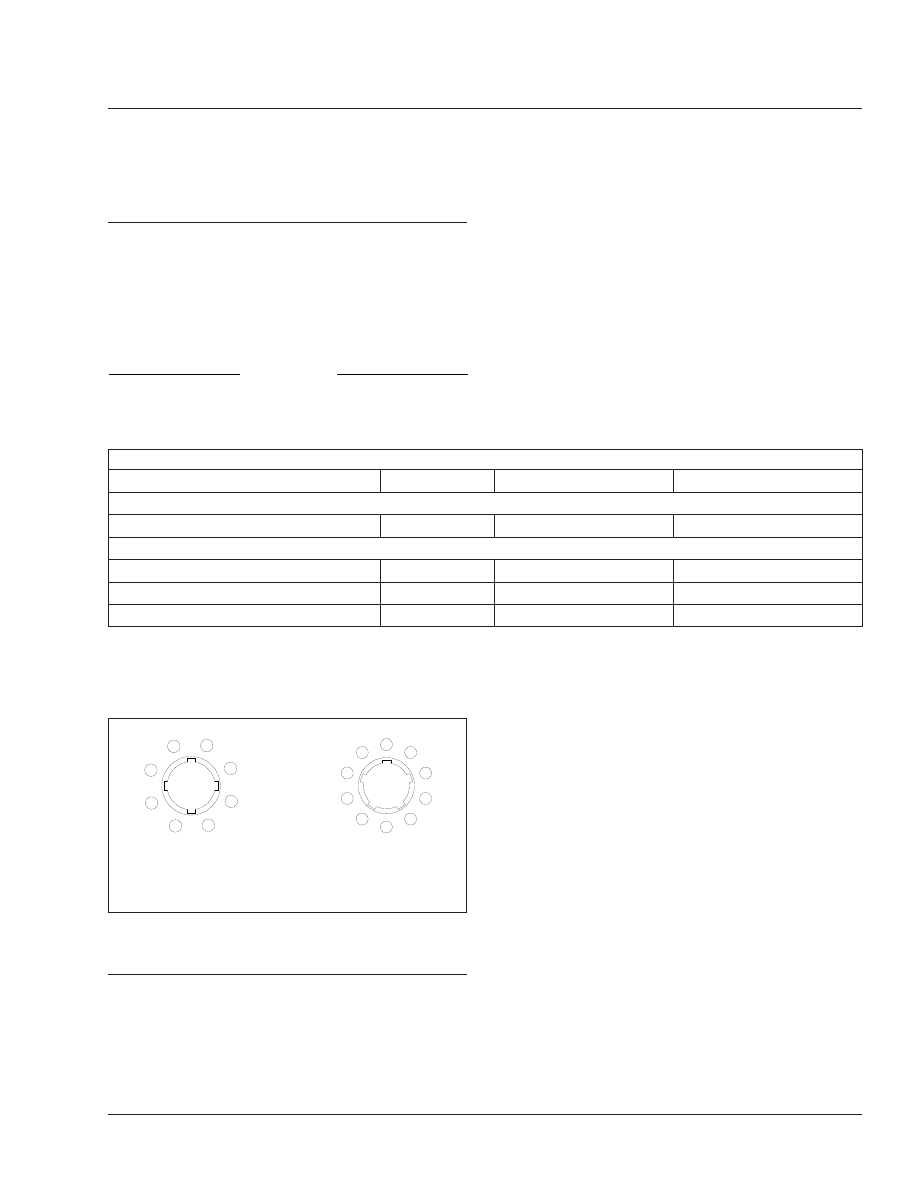
40–01 Wheel Nut Check

IMPORTANT: After a wheel has been installed,
the wheel nut torque must be rechecked after
50 to 100 miles (80 to 160 km) of operation.

See

Table 1

for disc wheel nut torque specifications,

and see

Fig. 1

for the wheel nut tightening se-

quence.

NOTICE

Insufficient wheel nut (rim nut) torque can cause
wheel shimmy, resulting in wheel damage, stud

breakage, and extreme tire tread wear. Excessive
wheel nut torque can break studs, damage
threads, and crack discs in the stud hole area.
Use the recommended torque values, and follow
the tightening sequence shown in

Fig. 1

.

When checking stud-piloted rear dual disc wheels
with inner and outer nuts, remove one outer nut at a
time, tighten the inner nut, then reinstall and tighten
the outer nut. Repeat this procedure for all wheel
nuts, using the tightening sequence shown in

Fig. 1

.

Disc Wheel Fastener Torques

Description

Nut Size

Wheel Manufacturer

Torque: lbf·ft (N·m)

10-Hole and 8-Hole Hub-Piloted Disc Wheel With Two-Piece Flange Nuts

*

Front and Rear Wheel Nut

M22 x 1.5

All

450–500 (610–678)

10-Hole Stud-Piloted Disc Wheel With Inner and Outer Nuts

Front Wheel Nut

1-1/8–16

All

450–500 (610–678)

Rear Wheel Inner Nut

3/4–16

All

450–500 (610–678)

Rear Wheel Outer Nut

1-1/8–16

All

450–500 (610–678)

*

Torque values for hub-piloted wheels are given for lubricated threads. Lubricate threads with SAE 30W engine oil. Do not apply thread lubricant to ball seats

of the nuts and wheels. Wipe it off if it is applied accidentally.

Torque values for stud-piloted wheels are given for clean, dry threads.

Table 1, Disc Wheel Fastener Torques

40–02 Tire Check

Tires should be inspected closely during the first
3000 to 10,000 miles (5000 to 16 000 km) for abnor-
mal wear.

Maintain the proper pressures for carried loads, per
the tire manufacturers’ recommendations, or the tire
pressure label on the driver’s door.

Have the wheel alignment checked after the first
10,000 miles (16 000 km), then every 40,000 miles
(60 000 km) thereafter.

Do not continue to drive the vehicle if tires develop
any of the following:

• blisters;
• cuts or punctures that reach to the cord;
• a nail, screw, rock, or other puncturing object;
• flat spots or irregular wear;
• tread worn to a minimum depth;
• inability to maintain proper tire pressure.

09/18/2001

A

B

f400164

1

10

8

6

3

5

4

9

2

7

1

2

4

6

7

5

8

3

A. 8-Stud Disc Wheel

B. 10-Stud Disc Wheel

Fig. 1, Wheel Nut Tightening Sequence

Wheels and Tires

40

40/1

Title of Maintenance Operation (MOP)

MOP Number

Driveline Inspection . . . . . . . . . . . . . . . . . . . . . . . . . . . . . . . . . . . . . . . . . . . . . . . . . . . . . . . . . . . . . . . . 41–01

Driveline Lubrication. . . . . . . . . . . . . . . . . . . . . . . . . . . . . . . . . . . . . . . . . . . . . . . . . . . . . . . . . . . . . . . . 41–02

Safety Precautions . . . . . . . . . . . . . . . . . . . . . . . . . . . . . . . . . . . . . . . . . . . . . . . . . . . . . . . . . . . . . . . . . 41–00

Driveline

41

Index, Alphabetical

41–00 Safety Precautions

Safety Precautions in this section apply to all
procedures within this group.

DANGER

When working on the vehicle, shut down the en-
gine, set the parking brake, and chock the tires.
Before working under the vehicle, always place
jack stands under the frame rails to ensure the
vehicle can not drop. Failure to follow these steps
could result in serious personal injury or death.

41–01 Driveline Inspection

1.

Park the vehicle on a flat, level surface, apply
the parking brakes, and chock the tires.

WARNING

Self-locking bearing-cup or bearing-strap cap-
screws must not be reused; replace the cap-
screws with new ones. Also, do not undertighten
or overtighten any bearing-cup or bearing-strap
capscrews. A loose or broken fastener at any
point in the driveline weakens the driveline con-
nection, which could cause serious vehicle dam-
age, or could result in a driveshaft separating
from the vehicle, possibly causing loss of vehicle
control that could result in serious personal injury
or death.

2.

Check the torque of the bearing-cup or bearing-
strap capscrews; see

Table 1

for installed torque

values.

Remove and discard any loose capscrews. Do
not reuse any loosened self-locking capscrews;
they are designed for one-time installation only.
Replace all loosened and removed capscrews
with new ones. Tighten the new capscrews as
specified in

Table 1

.

For half-round yokes with bearing straps , tighten
the bearing-strap capscrews following the tight-
ening sequence shown in

Fig. 1

in increments

of 20 lbf·ft (25 N·m) to the torque specifications
listed in

Table 1

.

Bearing Cap or Bearing Strap Capscrew Torque

Specifications

U-Joint Type

Torque: lbf·ft (N·m)

Half-Round Yokes with Bearing
Straps and 3/8-inch Capscrews
(see

Fig. 2

Ref. 8)

45–60 (60–80)

Half-Round Yokes with Bearing
Straps and 1/2-inch Capscrews (

Fig. 2

Ref. 8)

130–135 (175–185)

Full-Round Yokes with Bearing
Cups (

Fig. 3

)

43 (58)

RPL Series U-Joints with
Bearing Cups (

Fig. 4

)

125 (169)

Table 1, Bearing Cap or Bearing Strap Capscrew

Torque Specifications

3.

Check the driveline yokes for cracks, and check
end-yokes for looseness; see

Fig. 2

.

Replace cracked yokes.

If any end-yoke can be moved in or out on its
shaft, or can be rocked on its shaft, disconnect
the driveshaft and U-joint from the yoke, then
check the drive component’s shaft seal for leak-
age or other visible damage that may have been
caused by the loose yoke. Replace the seal if
needed, then tighten the yoke nut. Refer to Sec-
tion 41.00, Specifications 400
of the 122SD and
Coronado Workshop Manual 
for torque specifica-

12/16/2008

f410529

2

1

2

1

Tighten the capscrews in a counterclockwise sequence,
starting with either number 1 position.

Fig. 1, Tightening Sequence, Half-Round Yoke Bearing

Strap Capscrews

Driveline

41

41/1

tions. If the yoke is still loose after tightening the
yoke nut, replace the end-yoke and yoke nut.

Replace the prevailing torque locknut (end-yoke
nut) if it was removed for yoke replacement, seal
replacement, or any other reason.

4.

Check U-joint assemblies for wear by moving the
driveshaft up and down, and from side to side. If
any movement of the U-joint cross in the bear-
ings can be felt or seen, replace the U-joint as-
sembly.

5.

Check if the midship bearing and mounting are
loose or have deteriorated, by attempting to
move the driveshaft up and down, and from side
to side. If the bearing is loose on its shaft, or
rattles, replace it. If the bearing mount is loose
on the frame, tighten the mounting fasteners to
the proper torque value. See Section 41.00,
Specifications 400 
of the 122SD and Coronado
Workshop Manual 
for torque specifications. Re-
place the midship bearing assembly if the rubber
cushion is deteriorated or oil-soaked.

f410067b

1

2

3

3

05/01/95

4

5

6

7

8

9

10

11

12

13

14

15

16

NOTE: Not all fasteners are shown.

1.

Transmission

2.

Transmission Output-Shaft
End-Yoke (half-round)

3.

U-Joint Assembly

4.

Bearing Plate Self-Locking
Capscrew

5.

Bearing Cup (for full-round
yoke)

6.

U-Joint Cross

7.

Bearing Cup (for half-round
yoke)

8.

Bearing Strap and Bearing-
Strap Capscrew

9.

Slip-Joint Assembly

10. Sleeve-Yoke (full-round)

11. Dust Cap
12. Splined Stub Shaft
13. Driveshaft Tube
14. Tube-Yoke (full-round)
15. Axle Input-Shaft End-Yoke

(half-round)

16. Rear Axle

Fig. 2, Components of a Basic Driveline

Driveline

41

41/2


Content   ..  19  20  21  22   ..