Freightliner Coronado 132 / 122SD. Manual - part 16


  Index      Freightliner     Freightliner Coronado 132, Freightliner 122SD - service repair manual


Search            


Content   ..  14  15  16  17   ..


Freightliner Coronado 132 / 122SD. Manual - part 16


IMPORTANT: To prevent voiding the warranty
on Barksdale height-control valves, note the fol-
lowing:

• Do not overtighten the bolts in the Barksdale

height-control valve housing. The bolts should
not be loose, and should not require tightening.
Only if necessary, tighten the valve housing
bolts 45 lbf·in (500 N·cm). Any damage to the
valve housing will void the warranty.

• Do not attempt to disassemble the Barksdale

valve body or the control lever. There are no
serviceable parts in the valve, and any disas-
sembly will void the warranty.

NOTICE

When removing or loosening a Barksdale height-
control valve from a mounting bracket, always
hold the valve-side mounting studs in place with
an Allen wrench while loosening or tightening the
nuts that attach the valve to the bracket. Because
the mounting studs are threaded into the valve
body, loosening the nuts without holding the
studs can tighten the studs, which can crush the
valve body and damage the valve. Conversely,
tightening the nuts without holding the studs can
back the studs out, causing a separation of the
two halves of the valve body, and possibly a leak.

1.

Park the vehicle on a level surface, using a light
application of the brakes. Do not apply the park-
ing brakes. Shift the transmission into neutral,
and build the secondary air pressure to at least
100 psi (690 kPa). Shut down the engine.

2.

Mark the location of the front and rear tires on
the floor, and chock the tires on one axle only.

3.

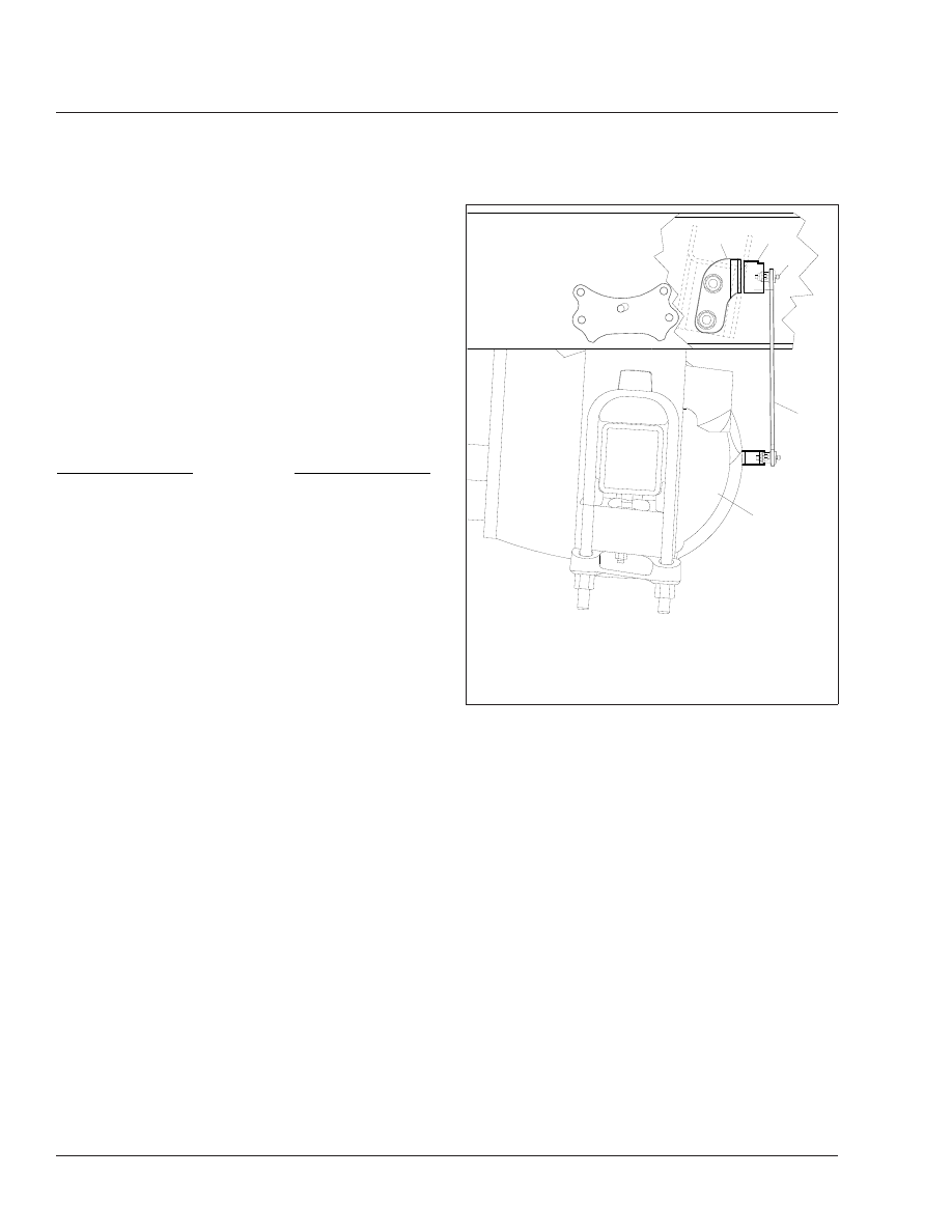
Check that the height-control valve vertical link-
age is connected and oriented correctly.

NOTE: The stud bolt that fastens the height-
control valve horizontal lever to the vertical link-
age is oriented correctly when the linkage rod is
vertical, as viewed from the side of the vehicle;
see

Fig. 6

The rod may be on the forward or

aft side of the lever to get it to be vertical.

4.

Measure the distance from the axle stop to the
top of the axle U-bolt pad. The correct distance
is determined by the axle and suspension con-
figurations; refer to Group 32 of the 122SD and
Coronado Workshop Manual 
for details.

5.

If the axle stop measurement is not correct, see
Group 32 of the 122SD and Coronado Work-
shop Manual 
for adjustment procedures.

6.

Apply the parking brakes, and remove the
chocks.

Chalmers Suspension

1.

Chock the front tires, place the transmission in
neutral, and release the parking brakes.

2.

Power wash the suspension, or clean it with a
hard-bristle brush before performing a visual in-
spection.

3.

Inspect the rubber bushings for cracks or other
damage.

Try to move the torque rod ends using your
hands only, and check for any free-play. If free-
play is felt, replace the torque rod end bushing.
Do not use a pry bar to check for free-play. Use

01/12/2000 

f320562a 

1.

Valve Mounting Bracket

2.

Height-Control Valve

3.

Stud Bolt

4.

Linkage Rod

5.

Axle

Fig. 6, Typical Barksdale Height-Control Valve

Installation (side view)

Suspension

32

32/4

of a pry bar may lead to premature bushing re-
placement.

4.

Lift the rear of the vehicle and support the frame
on jack stands to unload the suspension compo-
nents. The vehicle is lifted high enough when the
beam ends are off of the saddles.

Inspect the walking beam for cracks or other
damage. If damage is found, replace the walking
beam.

Keep the vehicle supported by the jack stands
for the next operation.

5.

Manipulate the walking beam so that a microm-
eter, vernier, or dial caliper can be used to deter-
mine the wear area thickness on the bottom
face. See

Fig. 7.

Measurements should be taken

a minimum of 1/2 inch from the beam flange
edges to eliminate any edge wear that may have
occurred. Subtract the wear area thickness (see

Fig. 7

Ref. B) from the thickness at the non-

wear area (see

Fig. 7

Ref. A) to determine the

amount of wear.

If the beams show any wear greater than 0.062
inch (1.5 mm), a Chalmers wear plate must be
installed, or the walking beam must be replaced.

6.

Rotate the restrictor cans 360 degrees and in-
spect the cans for cracks, severe corrosion, and
distortion. If any of these conditions are present,
or the restrictor can is missing, replace the re-
strictor can.

WARNING

Replace all cracked or missing restrictor cans.
Failure to do so could lead to loss of vehicle con-
trol, which could result in property damage, seri-
ous personal injury, or death.

32–02 Suspension Lubrication

Front Suspension

Wipe all dirt away from the grease fittings (if
equipped) on the spring-eye bushings. Apply multi-
purpose chassis grease with a pressurized grease
gun until old grease is forced out.

NOTE: Service Schedule IV vehicles equipped
with a 12,000 lb (5452 kg) front axle are fitted

with maintenance-free rubber bushings, and do
not require lubrication.

Rear Suspension

Chalmers

No lubrication is required on the Chalmers rear
suspension.

Freightliner Spring

Single Axle

No lubrication is required on Freightliner single axle
rear suspensions.

Tandem Axle

Lubricate the equalizer cap-and-tube assembly bush-
ings by applying multipurpose chassis grease at the
grease fitting until old grease is forced out from the
cap-and-tube assembly; see

Fig. 8

.

Hendrickson

The Hendrickson RS Series suspension does not
require lubrication.

09/27/95

f320432

1

A

B

A. Non-Wear Area

B. Wear Area

1.

Walking Beam

Fig. 7, Walking Beam End Wear Thickness

Suspension

32

32/5

For Hendrickson RT2 and RTE2 Series, lubricate the
bronze, ball-indented bushings in the spring eye, as
follows:

1.

Park the vehicle on a level surface, apply the
parking brakes, and chock the front tires.

2.

Raise the rear of the vehicle until the rear wheels
are suspended in the air, then support the ve-
hicle with safety stands. This relieves the load on
the bushings and pins to allow the proper flow of
lubricant around them.

3.

Use a multipurpose chassis grease and lubricate
the bronze, ball-indented bushings in the spring
eyes at the grease fitting; see

Fig. 9

Continue to

lubricate until grease exits both ends of the
bushing. If the pin will not accept lubricant, re-
move the pin and clean the lubrication channels
where lubricant may have hardened. Lower the
vehicle and remove the safety stands.

32–03 Suspension U-Bolt

Torque Check

NOTICE

Failure to retorque the U-bolt nuts could result in
spring breakage and abnormal tire wear.

1.

Park the vehicle on a flat surface, apply the park-
ing brakes, and chock the tires.

2.

Check the U-bolt torque in a diagonal pattern.
Set a click-type torque wrench to the highest
torque value for the fastener being checked. See

Table 1

for U-bolt torque specifications. Turn the

wrench in a clockwise motion (looking up) until
the torque wrench clicks.

Spring Assembly U-Bolt High Nut Torque Values

*

Size

Torque: lbf·ft (N·m)

5/8–18

Stage 1: Hand Tighten
Stage 2: 60 (81)
Stage 3: 200 (271)
Stage 4: 180 to 230 (245 to 313)

3/4–16

Stage 1: Hand Tighten
Stage 2: 60 (81)
Stage 3: 200 (271)
Stage 4: 270 to 330 (367 to 449)

7/8–14

Stage 1: Hand Tighten
Stage 2: 60 (81)
Stage 3: 200 (271)
Stage 4: 420 to 500 (571 to 680)

1–14

Stage 1: Hand tighten
Stage 2: 60 (81)
Stage 3: 200 (271)
Stage 4: 520 to 600 (707 to 816)

*

Tighten in a diagonal pattern as shown in

Fig. 10

.

Table 1, Spring Assembly U-Bolt High Nut Torque

Values

320020a

05/27/93

1

1

A

A. Lubricate here.
1.

Cap-and-Tube Assembly Bushing

Fig. 8, Equalizer Assembly Lubrication

09/15/95

f320424

1

2

2

3

4

4

1.

Bronze Bushing

2.

Lubrication Hole

3.

Grease Fitting

4.

Lubrication Groove

Fig. 9, Hendrickson RT2 and RTE2 Series Bushing

Lubrication

Suspension

32

32/6

03/10/2011

f320783    

1    

2    

3    

4    

Fig. 10, Tightening Pattern for U-Bolt High Nuts

Suspension

32

32/7


Content   ..  14  15  16  17   ..