Freightliner Coronado 132 / 122SD. Manual - part 12


  Index      Freightliner     Freightliner Coronado 132, Freightliner 122SD - service repair manual


Search            


Content   ..  10  11  12  13   ..


Freightliner Coronado 132 / 122SD. Manual - part 12


NOTICE

A leaking air filter or air lines can cause slow or
hard shifting of the transmission, and eventual
transmission damage.

7.

Start the engine, and build pressure in the air
system. Check for air leaks at the filter housing
and air line connections; repair any leaks.

26–04 Allison Transmission

Fluid and Filter Change

When draining transmission fluid, check for evidence
of dirt or water contamination. A small amount of
condensation will appear in the fluid during operation.

Water contamination is normally characterized as a
milky discoloration of the transmission fluid. Obvious
contamination of the transmission fluid indicates a
leak between the water and fluid areas of the trans-
mission cooler. Inspect and pressure-test the cooler
to confirm the leak; replace leaking transmission
coolers.

1.

If the transmission fluid is not at normal operat-
ing temperature, run the engine until the fluid
reaches operating temperature: 160 to 200°F (71
to 93°C).

2.

Park the vehicle on a level surface, apply the
parking brakes, and chock the tires.

3.

Clean the area around the drain plug and the
transmission fluid pan. Place a drain pan under
the transmission and remove the drain plug. Ex-
amine the fluid as it drains.

4.

Remove the 12 mounting bolts (six each) from
the two filter covers.

NOTE: A considerable amount of fluid will drain
when the filter covers are removed.

5.

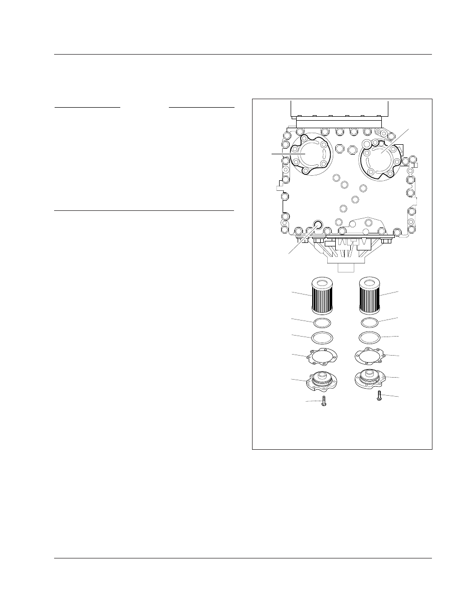
Remove the filter covers, O-rings, and two
square-cut seals from the transmission. See

Fig. 5

.

6.

Remove the filters from the bottom of the control
module.

7.

Lubricate the new O-rings with transmission fluid,
then install them on the cover assemblies.

8.

Install a new square-cut seal on each cover as-
sembly, then install the fluid filter elements on
the cover assemblies.

9.

Install the filter and cover assemblies into the
filter compartment.

1

1

f260317b

09/15/2009

7

1

1

2

2

3

3

4

4

5

5

6

6

1.

Filter Cover

2.

Filter Element

3.

Filter Element O-Ring

4.

Square-Cut Seal

5.

Gasket

6.

Capscrew

7.

Drain Plug

Fig. 5, Allison Transmission Filter Location and

Components

Transmission

26

26/5

10. Align each cover assembly with the holes in the

channel plate sump, and push the cover assem-
blies in by hand to seat the seals.

NOTICE

Do not use the bolts to draw the filter covers to
the sump. This can damage the covers, seals, or
sump.

11. Install six bolts in each cover, and torque the

bolts 38 to 44 lbf·ft (51 to 61 N·m).

12. Replace the drain plug O-ring, then install the

drain plug. Tighten the drain plug 18 to 24 lbf·ft
(25 to 32 N·m).

13. Refill the transmission with fresh automatic trans-

mission fluid and check the fluid level. See

Table 3

for transmission lubricant capacities, and

Table 4

for approved transmission lubricants.

Allison 4000 Series Transmission Lubricant

Capacities

*

Sump Size

Refill Capacity : qt (L)

4 Inch

39 (37)

2 Inch

31 (30)

*

Quantities listed are approximate. Add listed amount of fluid, then perform

a "hot check" and add fluid as needed. Do not overfill.

Add 3 qt (2.8 L) for transmissions with PTO.

Table 3, Allison 4000 SeriesTransmission Lubricant

Capacities

Allison Approved Automatic Transmission Lubricants

Transmission

Lubricant Type

*

Allison 4000 Series

Castrol TranSynd (synthetic)
or other
Allison Approved TES 295 Fluid

Allison Approved TES 389 Fluid
or
Dexron®-VI

IMPORTANT: For TES 389 and
Dexron-VI, use maintenance
interval M1.

*

Lubricants listed in order of preference. Do not mix fluid types. Call 1-800-

252-5283, or see

www.AllisonTransmission.com

for a complete list of Alli-

son approved lubricants.

Dexron-VI may only be used in units beginning with S/N 6610220990.

Table 4, Allison Approved Automatic Transmission

Lubricants

Transmission

26

26/6

Title of Maintenance Operation (MOP)

MOP Number

Fifth Wheel Inspection . . . . . . . . . . . . . . . . . . . . . . . . . . . . . . . . . . . . . . . . . . . . . . . . . . . . . . . . . . . . . . 31–01

Fifth Wheel Lubrication. . . . . . . . . . . . . . . . . . . . . . . . . . . . . . . . . . . . . . . . . . . . . . . . . . . . . . . . . . . . . . 31–02

Frame Fastener Torque Check . . . . . . . . . . . . . . . . . . . . . . . . . . . . . . . . . . . . . . . . . . . . . . . . . . . . . . . . 31–03

Premier 690 Coupling Inspection. . . . . . . . . . . . . . . . . . . . . . . . . . . . . . . . . . . . . . . . . . . . . . . . . . . . . . . 31–05

Safety Precautions . . . . . . . . . . . . . . . . . . . . . . . . . . . . . . . . . . . . . . . . . . . . . . . . . . . . . . . . . . . . . . . . . 31–00

Trailer Electrical Connector Lubricating . . . . . . . . . . . . . . . . . . . . . . . . . . . . . . . . . . . . . . . . . . . . . . . . . . 31–04

Frame and Frame Components

31

Index, Alphabetical

31–00 Safety Precautions

Safety Precautions in this section apply to all
procedures within this group.

DANGER

When working on the vehicle, shut down the en-
gine, set the parking brake, and chock the tires.
Before working under the vehicle, always place
jack stands under the frame rails to ensure the
vehicle can not drop. Failure to follow these steps
could result in serious personal injury or death.

31–01 Fifth Wheel Inspection

WARNING

All fifth wheel maintenance, adjustment, and re-
building must be done only by a qualified me-
chanic. Improper or incomplete procedures could
result in a possible disengagement of the trailer
from the tractor, which could result in personal
injury or property damage.

Parts are under spring compression. Wear safety
goggles while servicing the fifth wheel. Failure to
do so can result in personal injury, due to parts
ejecting with force.

Holland FWS1

1.

Disconnect the tractor from the trailer. For in-
structions, see the vehicle Driver’s/Operator’s
Manual.

2.

Thoroughly steam clean the fifth wheel.

3.

Check the fifth wheel plate for cracks. Check for
sharp edges on top; the chamfer should be 1/8
to 1/4 inch (3 to 6 mm).

4.

When the wheel is locked, the safety latch must
swing free and fall freely into position. See

Fig. 1

.

5.

The lever bar and release handle must be in
proper alignment. See

Fig. 2

Compare the lever

bar and release handle alignment to a new, or a
properly operating lever bar and release handle.
Replace any bent or misaligned lever bar or re-
lease handle.

f311052

10/29/2007

1

2

3

4

1.

Lubricant Grooves

2.

Safety Latch

3.

Release Handle

4.

Mount

Fig. 1, Holland FWS1 Fifth Wheel

03/28/2013

f311140

1

2

1.

Release Handle

2.

Lever Bar

Fig. 2, Lever Bar and Release Handle Alignment

Frame and Frame Components

31

31/1


Content   ..  10  11  12  13   ..