Freightliner Coronado 132 / 122SD. Manual - part 13


  Index      Freightliner     Freightliner Coronado 132, Freightliner 122SD - service repair manual


Search            


Content   ..  11  12  13  14   ..


Freightliner Coronado 132 / 122SD. Manual - part 13


6.

Check all cotter pins for cracking or damage. Re-
place any cotter pin that shows any signs of
damage.

7.

Check all mounting bolts for signs of fatigue, and
tighten them to the proper torque. For torque
specifications, see Group 00 of the vehicle
Workshop Manual. Inspect all angles, plates, and
brackets for cracks or other damage.

8.

Replace cracked, worn, or damaged parts with
new parts. Replace all loose mounting bolts with
5/8–11 SAE grade 8 bolts, grade C locknuts, and
hardened washers. Do not re-use bolts, nuts,
and washers on fifth wheel mountings.

9.

After inspecting the fifth wheel, lubricate all mov-
ing parts with a chassis or multipurpose grease.
See MOP 31–02 for lubrication instructions.

Holland FW35

1.

Disconnect the tractor from the trailer. For in-
structions, see the vehicle Driver’s/Operator’s
Manual.

2.

Thoroughly steam clean all fifth wheel compo-
nents before inspection.

3.

Check for cracks in the fifth wheel assembly,
mounting brackets, and mounting parts.

4.

Check the fastener torques on the fifth wheel
assembly and fifth wheel mounting. Tighten bolts
and nuts as needed. Replace missing or dam-
aged bolts.

5.

Inspect the fifth wheel for bent, worn, damaged,
and missing parts; replace them as needed with
genuine Holland parts.

6.

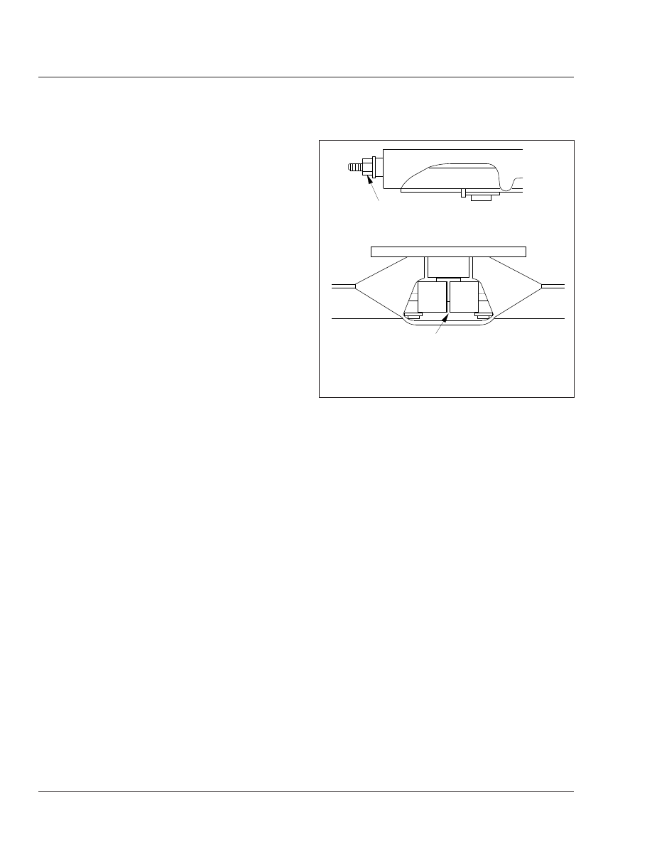
Using a Holland Kingpin Lock Tester (Holland
tool number TF-TLN-5001, available through the
PDCs as HLD TFTLN5001), check the operation
of the locking mechanism by opening and closing
the locks. See

Fig. 3

.

7.

After inspecting the fifth wheel, lubricate all mov-
ing parts with a chassis or multipurpose grease.
See MOP 31–02 in this manual for lubrication
instructions.

Fontaine

1.

Disconnect the tractor from the trailer. For in-
structions, see the vehicle Driver’s/Operator’s
Manual.

2.

Thoroughly steam clean the fifth wheel.

3.

Check for cracks in the fifth wheel assembly,
mounting brackets, and mounting parts.

4.

Ensure that both bracket pins are in place and
secured by retainer pins and cotter pins. See

Fig. 4

.

5.

For fifth wheels equipped with bracket liners,
rock the fifth wheel. If it does not rock freely, re-
move the top plate and inspect the bracket lin-
ers. Replace liners that are broken or less than
0.125 inch (3 mm) thick at the top of the liners.
For the liner replacement procedure, see the
Fontaine website,

www.fifthwheel.com

.

6.

Check the jaw and stationary jaw for mushroom-
ing, and check that the serrations at the jaw and
wedge are in good condition.

7.

Test the secondary safety lock latch for ease of
operation.

8.

Check for loose nuts or bolts on the fifth wheel
and the mounting. Set a torque wrench to the
maximum torque value for the bolt being
checked, and confirm that the torque is to speci-
fication. Do not loosen the bolt to check the
torque. For torque specifications, see Group 00
of the vehicle Workshop Manual.

04/11/2011

f310887

A

B

A. The nut and washer should be snug against the fifth

wheel.

B. The locks should be completely closed around the

kingpin.

Fig. 3, Holland Fifth Wheel Properly Closed

Frame and Frame Components

31

31/2

12/02/2010

f311134

1

2

2

3

4

5

5

6

7

8

8

9

10

11

12

12

12

13

14

15

16

8

7

6

5

5

8

17

12

12

18

15

19

20

21

22

23

12

12

24

15

25

26

27

NOTE: 6000 Series shown; 7000 Series fifth wheels use similar parts.

1.

Wedge Stop Rod Nut

2.

Flat Washer, 5/8"

3.

Wedge Stop Rod Spring

4.

Wedge Stop Rod

5.

Grease Fitting

6.

Bracket Pin

7.

Bracket Retainer Pin

8.

Cotter Pin, 3/16" x 1"

9.

Bumper Spring

10. Handle Spring

11. Bolt, Secondary Safety Lock
12. Flat Washer
13. Secondary Safety Lock
14. Bushing, Secondary Safety

Lock

15. Hex Locknut
16. Pull Handle
17. Bolt, Bumper
18. Bushing

19. Bumper
20. Timer Spring
21. Timer
22. Operating Handle
23. Bolt, Operating Handle
24. Bushing, Operating Handle
25. Hair Pin Cotter
26. Wedge
27. Step Jaw

Fig. 4, Fontaine Fifth Wheel

Frame and Frame Components

31

31/3

9.

Check all springs to see if they are securely fas-
tened, and are not deformed.

WARNING

Do not disassemble the fifth wheel to inspect the
springs. The springs are under extreme pressure,
and could cause serious injury.

10. Check the wedge adjustment.

10.1

Close the fifth wheel on a standard 2-inch
(50-mm) kingpin or similar 2-inch (50-mm)
diameter shaft so that it locks.

10.2

Push on the wedge stop rod with hand
pressure. It should move in 1/4 inch (6
mm) and spring back out on release.

If the free travel is not 1/4 inch (6 mm),
adjust the distance to 1/4 inch (6 mm) by
turning the wedge stop rod, on the right
side of the top plate, clockwise to reduce
the gap and counter-clockwise to in-
crease it.

11. Replace cracked, worn, or damaged parts with

new parts. Replace all loose mounting bolts with
5/8–11 SAE grade 8 bolts, grade C locknuts, and
hardened washers. Do not re-use bolts, nuts,
and washers on fifth wheel mountings.

12. After inspecting the fifth wheel, lubricate all mov-

ing parts with a chassis or multipurpose grease.
Apply a generous coating of grease to the top
plate to fill the grooves, or depressions, on the
top plate. See MOP 31–02 in this manual for lu-
brication instructions.

Jost

1.

Disconnect the tractor from the trailer. For in-
structions, see the vehicle Driver’s/Operator’s
Manual.

2.

Thoroughly steam clean the fifth wheel.

3.

Check the mounting for missing or damaged fas-
teners, and broken components. Replace or re-
pair as needed.

4.

Inspect the bracket pin bolts. Make sure the lock-
ing tabs are properly securing the bolts in place.
See

Fig. 5

.

5.

Check the fifth wheel for bent, worn, or broken
parts. Replace as needed.

6.

If the fifth wheel is equipped with low-lube plates,
check the plates and replace if damaged or worn
down to the securing bolts. It is normal for out-
side edges of the plate to pucker slightly; this
does not affect performance.

7.

Check the fifth wheel adjustment. Using a lock
tester, lock and unlock the fifth wheel several
times. Make sure that the locking mechanism
works properly.

The lock is properly adjusted if: the wheel locks
and unlocks easily each time and the lock tester
rotates freely.

The lock is too loose if: you feel fore-aft play
when pulling and pushing on the lock tester
handle. See

Fig. 6

Ref. A.

The lock is too tight if: the lock tester does not
rotate freely in the lock. See

Fig. 6

Ref. B.

8.

If the lock is improperly adjusted, correct as fol-
lows.

If the lock is too tight, loosen the jam nut, turn
the adjustment bolt clockwise one full turn, then
reset the jam nut. Lock and unlock the mecha-
nism several times to test. Repeat if necessary.
See

Fig. 7

.

If the lock is too loose, loosen the jam nut, turn
the adjustment bolt counterclockwise one full
turn, then reset the jam nut. Lock and unlock the
mechanism several times to test. Repeat if nec-
essary. See

Fig. 7

.

9.

If the fifth wheel is equipped with a sliding
mechanism, inspect and adjust it as follows.

09/01/2009

f311101

Fig. 5, Bracket Pin Bolt Locking Tabs

Frame and Frame Components

31

31/4

9.1

Check the bracket for any cracks or miss-
ing and damaged parts.

9.2

Inspect the locking plungers for full en-
gagement.

9.3

Check the locking mechanism for proper
operation.

If the plungers will not release, check the
air cylinder or plunger adjustment.

If the plungers are loose, check the
plunger adjustment and the plunger
springs for proper compression. Replace
if needed.

9.4

The outboard slider assembly requires no
adjustment. If the plungers are loose, in-
spect and replace locking mechanism
parts as needed.

9.5

The inboard slider is adjustable for frame
width and plunger engagement. For ad-
justment, refer to the fifth wheel installa-
tion instructions.

10. Replace cracked, worn, or damaged parts with

new parts. Replace all loose mounting bolts with
5/8–11 SAE grade 8 bolts, grade C locknuts, and

09/01/2009

f311099      

A

B

C

D

E

F

G

H

A. Checking for fore/aft play.
B. Rotating tester in lock.
C. Engage hook.
D. Pull/push handle fore/aft.
E. Check for movement of kingpin in lock.
F.

Disengage hook.

G. Push/pull handle inboard/outboard.
H. Rotate lock tester.

Fig. 6, Jost Fifth Wheel Adjustment

09/02/2009


3

1

2

f311100

1.

Jam Nut

2.

Adjustment Bolt

3.

Grease Zerk

Fig. 7, Jost Fifth Wheel

Frame and Frame Components

31

31/5


Content   ..  11  12  13  14   ..