Freightliner Century Class. Manual - part 11


  Index      Freightliner     Freightliner Century Class - service manual 2016 year


Search            


Content   ..  9  10  11  12   ..


Freightliner Century Class. Manual - part 11


10.1

Connect the halves of the fan solenoid
connector.

10.2

Turn the air conditioner off.

10.3

Start the engine and charge the air sys-
tem to 120 psi (827 kPa). Tests must be
performed with the engine temperature
below 205°F (96°C) for Caterpillar en-
gines, and below 200°F (93°C) for Cum-
mins and Detroit Diesel engines.

10.4

Set the toggle switch to the ON position;
the fan clutch should engage.

10.5

Apply the foot brake, and release the
parking brakes.

10.6

Set the toggle switch to the AUTO or OFF
position; the air should exhaust and the
fan clutch should disengage. Replace the
switch if necessary.

11. If the fan stays engaged at all times on a Detroit

Diesel engine, check the circuit breaker labeled
"engine fan."

Kysor K22RA Fan Clutch

1.

Disconnect the electrical cables from the battery.
Drain all air from the air system. If equipped with
an air starter, drain the air starter reservoir.

WARNING

If the engine starts during this procedure, the fan
could cause personal injury. If the vehicle is
equipped with an air starter, be sure that the air
starter reservoir is drained.
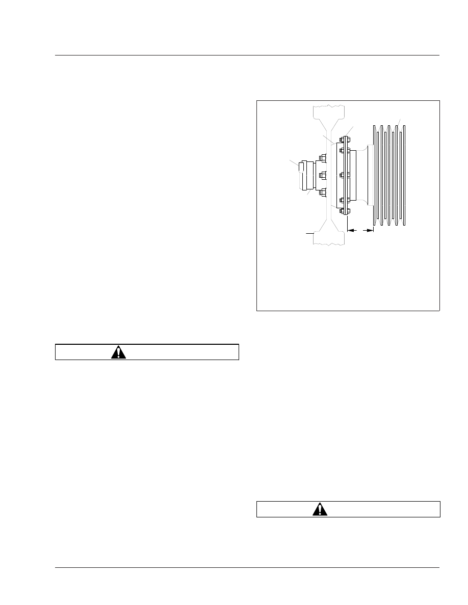
2.

Measure the distance from the back surface of
the fan clutch retaining plate to the forward-most
edge of the fan belt pulley. See

Fig. 9

Ref. A.

3.

Disconnect the line from the air inlet of the air
cylinder. Connect a shop air hose to the inlet.

4.

Apply a minimum of 100 psi (690 kPa) air pres-
sure to the air cylinder—the bearing housing will
move backwards, disengaging the clutch. Again,
measure the distance from the back surface of
the retaining plate to the forward-most edge of
the fan belt pulley.

5.

Compare the two measurements; if the difference
between the two measurements exceeds 0.150
inches (3.8 mm), the clutch lining is worn and
must be replaced. See Group 20 of the Century

Class Trucks Workshop Manual for clutch lining
replacement instructions.

6.

Release the air pressure, then disconnect the
shop hose from the air inlet of the air cylinder.
Connect the vehicle air hose to the inlet.

7.

Connect the electrical cables to the battery.

8.

Start the engine.

Horton DriveMaster® Fan Clutch

NOTE: If any part of the fan clutch needs to be
repaired or replaced after performing the checks
below, see Group 20 of the Century Class
Trucks Workshop Manual
.

1.

Disconnect the batteries at the negative termi-
nals. Drain all air from the air system. If
equipped with an air starter, drain the air starter
reservoir.

WARNING

Make sure the batteries are disconnected before
checking the fan clutch. If the engine starts during

f200237a

1

2

3

4

5

6

05/27/93

A

With the fan clutch engaged, measure the distance at A;
measure it again with the fan clutch disengaged.

1.

Bearing Housing

2.

Retaining Plate

3.

Fan Pulley

4.

Air Inlet (from solenoid
valve)

5.

Air Cylinder

6.

Fan

Fig. 9, Kysor K22RA Fan Clutch Lining Wear Checking

Engine Cooling/Radiator

20

20/7

this procedure, the fan could engage, which could
result in serious personal injury.

2.

Inspect the electrical connections and wires to
the fan clutch solenoid. Secure the connection if
loose; replace wires and connectors if damaged.

3.

Clean the fan clutch air solenoid valve filter, if
equipped.

3.1

Unscrew the fan clutch solenoid valve air
filter assembly and remove the filter ele-
ment.

3.2

Clean the filter element with cleaning sol-
vent.

3.3

Using a clean, lint free cloth, wipe off any
excess solvent.

3.4

Reassemble the clutch valve solenoid air
filter assembly and install on the vehicle.

4.

Visually check the fan for bent, cracked, or dam-
aged blades. Replace if damaged. Check for ad-
equate clearance between the fan and other
components.

5.

Check the fan belt for wear, tension, and align-
ment. Correct, if necessary.

6.

Check for wear on the friction facing. Replace
the friction facing if it is worn to a 3/16-inch (4.8-
mm) thickness or less. Also check the facing for
signs of oil contamination or burn marks. If evi-
dence of oil or burn marks are found, replace the
friction facing.

7.

Connect the battery cables. Start the engine, and
charge the air system to 120 psi (827 kPa).
Manually engage and disengage the fan clutch.

Check the fan and the fan clutch from a dis-
tance. Look for vibration, fan blade contact, fan
clutch slippage, and overall fan clutch operation.

If the fan clutch does not operate correctly, see
Group 20 of the Century Class Trucks Workshop
Manual 
for troubleshooting and repair proce-
dures.

8.

With the air system charged to 120 psi (827
kPa), check the fan clutch for audible air leaks,
using a suitable listening device.

Check at the solenoid valve, the air filter assem-
bly, and the air hoses and fittings. See

Fig. 10

.

Using a wet finger or a soapy water solution,
check for a leak in the same areas.

9.

If a leak is detected, remove the fan blade. In-
stall a new seal kit. See Group 20 of the
Century Class Trucks Workshop Manual for re-
pair procedures.

10. Check the fan drive for discoloration or any other

signs of slipping or overheating.

NOTE: The fan clutch may slip if the air supply
pressure is below 70 psi (483 kPa) or if there is
a leak inside the fan clutch. Any leak must be
remedied.

11. Check the fan clutch bearings.

11.1

Turn the fan in both directions and feel
for worn hub bearings.

11.2

If possible, remove the drive belt and
check for worn sheave bearings by turn-
ing the sheave in both directions.

11.3

If either the hub or sheave bearings are
worn, replace them, using a Horton Drive-
Master Super Kit.

For instructions and kit part number, see
Group 20 of the Century Class Trucks
Workshop Manual
.

f200581

05/30/2002

Fig. 10, Checking for Air Leaks (Horton DriveMaster)

Engine Cooling/Radiator

20

20/8

MOP Number

Clutch Release Cross-Shaft Lubrication. . . . . . . . . . . . . . . . . . . . . . . . . . . . . . . . . . . . . . . . . . . . . . . . . . 25–02

Eaton Fuller Clutch Release Bearing Lubrication . . . . . . . . . . . . . . . . . . . . . . . . . . . . . . . . . . . . . . . . . . . 25–01

Meritor Clutch Release Bearing Lubrication. . . . . . . . . . . . . . . . . . . . . . . . . . . . . . . . . . . . . . . . . . . . . . . 25–04

Safety Precautions . . . . . . . . . . . . . . . . . . . . . . . . . . . . . . . . . . . . . . . . . . . . . . . . . . . . . . . . . . . . . . . . . 25–00

Sleeve Assembly Bronze Bushing Lubrication . . . . . . . . . . . . . . . . . . . . . . . . . . . . . . . . . . . . . . . . . . . . . 25–03

Clutch

25

Index, Alphabetical

25–00 Safety Precautions

Safety Precautions in this section apply to all
procedures within this group.

DANGER

When working on the vehicle, shut down the en-
gine, set the parking brake, and chock the tires.
Before working under the vehicle, always place
jack stands under the frame rails to ensure the
vehicle can not drop. Failure to follow these steps
could result in serious personal injury or death.

25–01 Eaton Fuller Clutch

Release Bearing
Lubrication

The standard clutch release bearing is sealed, and
does not require lubrication. If the vehicle is
equipped with an optional clutch release bearing with
a grease fitting, lubricate the bearing as follows:

1.

Park the vehicle on a level surface. Apply the
parking brakes, and chock the rear tires.

2.

Remove the clutch inspection plate.

NOTE: Some clutch release bearings are
equipped with a lubrication extension that ex-
tends outside of the clutch housing. It is not
necessary to remove the clutch inspection plate
when the lubrication extension is used.

NOTE: For lubrication of the release bearing,
Eaton fuller recommends a lithium-base high-
temperature grease that meets the NLGI grade
one or two specification.

3.

Wipe any dirt away from the grease fitting. See

Fig. 1

Use a pressure-type grease gun

equipped with the recommended grease, and
lubricate the bearing until excess grease purges
from the rear of the release bearing (toward the
transmission).

CAUTION

Do not over-lubricate the clutch release bearing.
Over-lubrication could contaminate the clutch in-
ternally, causing clutch slippage and premature

failure. Do not use chassis grease or multipurpose
lubricants.

4.

Wipe off excess grease and apply it to both the
yoke-finger and the sleeve-bushing contact
points. See

Fig. 2

.

5.

Install the clutch inspection plate.

6.

Remove the chocks.

f250081a

05/27/93

Fig. 1, Release Bearing Grease Fitting

08/10/2009

f250444

1

2

1.

Sleeve-Bushing Contact Point

2.

Yoke-Finger Contact Points

Fig. 2, Grease the Contact Points

Clutch

25

25/1


Content   ..  9  10  11  12   ..