Freightliner Century Class. Manual - part 10
7.3
Gradually, apply air pressure to help dis-
lodge sediment built up in the radiator
core. Do not apply more than 15 psi (103
kPa) air pressure to the radiator. Pres-
sures exceeding 15 psi (103 kPa) could
damage the radiator core.
7.4
Shut off the air at the pressure gun
nozzle and allow the radiator to refill with
water.
7.5
Repeat the previous two steps until clean
water flows from the radiator.
7.6
Remove the radiator side tank drain plug
and allow the radiator to drain.
8.
Connect the hoses. The hose clamps on the
main radiator can be either T-bolt clamps (see
) or Breeze Constant-Torque clamps (see
When working with T-bolt hose clamps, tighten
the clamps 55 lbf·in (620 N·cm). These clamps
are now standard on hoses with an inside diam-
eter greater than 2 inches (51 mm).
When installing Breeze Constant-Torque hose
clamps, the clamps must be tightened to the cor-
rect torque. The screw tip of the clamp must ex-
tend about 1/4 inch (6 mm) from the clamp hous-
ing, and the Belleville washer stacks must be
collapsed almost flat. Use a torque wrench to
08/19/2009
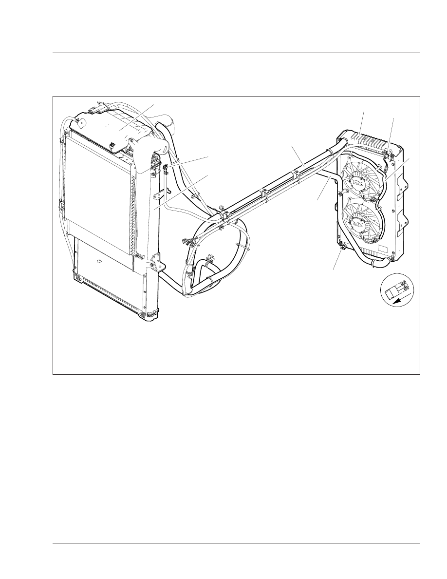
f200726
1
2
3
4
5
6
7
8
9
NOTE: The main radiator drain plug is not shown.
1.
Surge Tank
2.
Remote Bleed Valve
3.
Main Radiator
4.
Auxiliary Radiator
5.
Auxiliary Radiator Temperature Sensor
6.
Fan Power Harness
7.
Auxiliary Radiator Drain Plug
8.
Cold Coolant Hose
9.
Hot Coolant Hose
Fig. 3, Coolant System, Argosy, with Auxiliary Radiator
Engine Cooling/Radiator
20
20/3