Dodge Dakota (ND). Manual - part 887


  Index      Dodge     Dodge Dakota (ND) 2005 - service repair manual 2005 year


Search            


Content   ..  885  886  887  888   ..


Dodge Dakota (ND). Manual - part 887


5. Clean threads in exhaust pipe using appropriate tap.

INSTALLATION

Threads of new oxygen sensors are factory coated with anti-seize compound to aid in removal. DO NOT add any
additional anti-seize compound to threads of a new oxygen sensor.

1. Install O2S sensor. Tighten to 30 N·m (22 ft. lbs.) torque.

2. Connect O2S sensor wire connector.

3. 4–Sensor System: If installing the right-upstream (2/1) sensor, install plastic inner fender liner, and right-front

tire/wheel.

4. Lower vehicle.

THROTTLE BODY

DESCRIPTION

The throttle body is located on the intake manifold. Fuel does not enter the intake manifold through the throttle body.
Fuel is sprayed into the manifold by the fuel injectors.

OPERATION

Filtered air from the air cleaner enters the intake manifold through the throttle body. The throttle body contains an air
control passage controlled by an Idle Air Control (IAC) motor. The air control passage is used to supply air for idle
conditions. A throttle valve (plate) is used to supply air for above idle conditions.

Certain sensors are attached to the throttle body. The accelerator pedal cable, speed control cable and transmission
control cable (when equipped) are connected to the throttle body linkage arm.

A (factory adjusted) set screw is used to mechanically limit the position of the throttle body throttle plate. Never
attempt to adjust the engine idle speed using this screw. 
All idle speed functions are controlled by the PCM.

REMOVAL

3.7L V-6

A (factory adjusted) set screw is used to mechanically
limit the position of the throttle body throttle plate.
Never attempt to adjust the engine idle speed
using this screw. 
All idle speed functions are con-
trolled by the Powertrain Control Module (PCM).

1. Remove air cleaner tube at throttle body.

2. Disconnect throttle body electrical connectors at

IAC motor and TPS.

3. Remove all control cables from throttle body (lever)

arm. Refer to the Accelerator Pedal and Throttle
Cable section for removal/installation procedures.

4. Disconnect necessary vacuum lines at throttle

body.

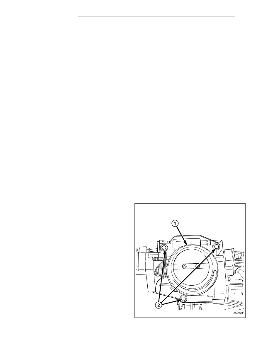
5. Remove three throttle body mounting bolts (2).

6. Remove throttle body from intake manifold.

14 - 46

FUEL INJECTION

ND

7. Check condition of old throttle body-to-intake man-

ifold o-ring (2).

4.7L V-8

1. Remove air duct and air resonator box at throttle

body.

2. Disconnect throttle body electrical connectors at

IAC motor and TPS (3) , (4), and (5).

3. Remove vacuum line at throttle body.

4. Remove all control cables from throttle body (lever)

arm. Refer to Accelerator Pedal and Throttle Cable.

5. Remove three throttle body mounting bolts (1).

6. Remove throttle body from intake manifold.

ND

FUEL INJECTION

14 - 47

INSTALLATION

3.7L V-6

1. Check condition of throttle body-to-intake manifold

o-ring (2). Replace as necessary.

2. Clean mating surfaces of throttle body and intake

manifold.

3. Install throttle body-to-intake manifold o-ring.

4. Install throttle body to intake manifold.

5. Install three mounting bolts (2). Tighten bolts to 12

N·m (105 in. lbs.) torque.

6. Install control cables.

7. Install electrical connectors.

8. Install necessary vacuum lines.

9. Install air plenum.

14 - 48

FUEL INJECTION

ND

4.7L V-8

1. Clean throttle body-to-intake manifold o-ring (2).

2. Clean mating surfaces of throttle body and intake

manifold.

3. Install throttle body to intake manifold by position-

ing throttle body to manifold alignment pins.

4. Install three mounting bolts (1). Tighten bolts to 12

N·m (105 in. lbs.) torque.

5. Install control cables.

6. Install vacuum line to throttle body.

7. Install electrical connectors.

8. Install air plenum.

CABLE-THROTTLE CONTROL

REMOVAL

3.7L V-6

CAUTION: Be careful not to damage or kink cable core wire (within cable sheathing) while servicing accel-
erator pedal or throttle cable.

1. From inside vehicle, hold up accelerator pedal.

Remove plastic cable retainer (clip) and throttle
cable core wire from upper end of pedal arm. Plas-
tic cable retainer (2) snaps into top of pedal arm.

2. Remove cable core wire at pedal arm.

3. From inside vehicle, remove metal clip holding

cable to dashpanel.

4. Remove air resonator box at throttle body.

5. Unsnap cable from dashpanel routing clip.

6. Remove cable housing from dash panel and pull

into engine compartment

.

ND

FUEL INJECTION

14 - 49


Content   ..  885  886  887  888   ..