Dodge Dakota (ND). Manual - part 886
The MAP sensor signal is provided from a single piezoresistive element located in the center of a diaphragm. The
element and diaphragm are both made of silicone. As manifold pressure changes, the diaphragm moves causing
the element to deflect, which stresses the silicone. When silicone is exposed to stress, its resistance changes. As
manifold vacuum increases, the MAP sensor input voltage decreases proportionally. The sensor also contains elec-
tronics that condition the signal and provide temperature compensation.
The PCM recognizes a decrease in manifold pressure by monitoring a decrease in voltage from the reading stored
in the barometric pressure memory cell. The MAP sensor is a linear sensor; meaning as pressure changes, voltage
changes proportionately. The range of voltage output from the sensor is usually between 4.6 volts at sea level to as
low as 0.3 volts at 26 in. of Hg. Barometric pressure is the pressure exerted by the atmosphere upon an object. At
sea level on a standard day, no storm, barometric pressure is approximately 29.92 in Hg. For every 100 feet of
altitude, barometric pressure drops 0.10 in. Hg. If a storm goes through, it can change barometric pressure from
what should be present for that altitude. You should know what the average pressure and corresponding barometric
pressure is for your area.
REMOVAL
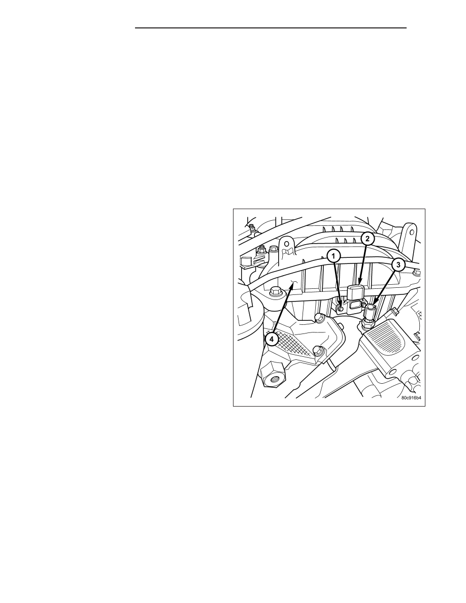
3.7L V-6
The Manifold Absolute Pressure (MAP) sensor (2) is
mounted into the front of the intake manifold.
1. Disconnect electrical connector at sensor.
2. Clean area around MAP sensor.
3. Remove two sensor mounting screws (1).
4. Remove MAP sensor from intake manifold.
14 - 42
FUEL INJECTION
ND