Index Dodge Dodge Dakota (ND) 2005 - service repair manual 2005 year
Search
Content .. 753 754 755 756 ..
Dodge Dakota (ND). Manual - part 755
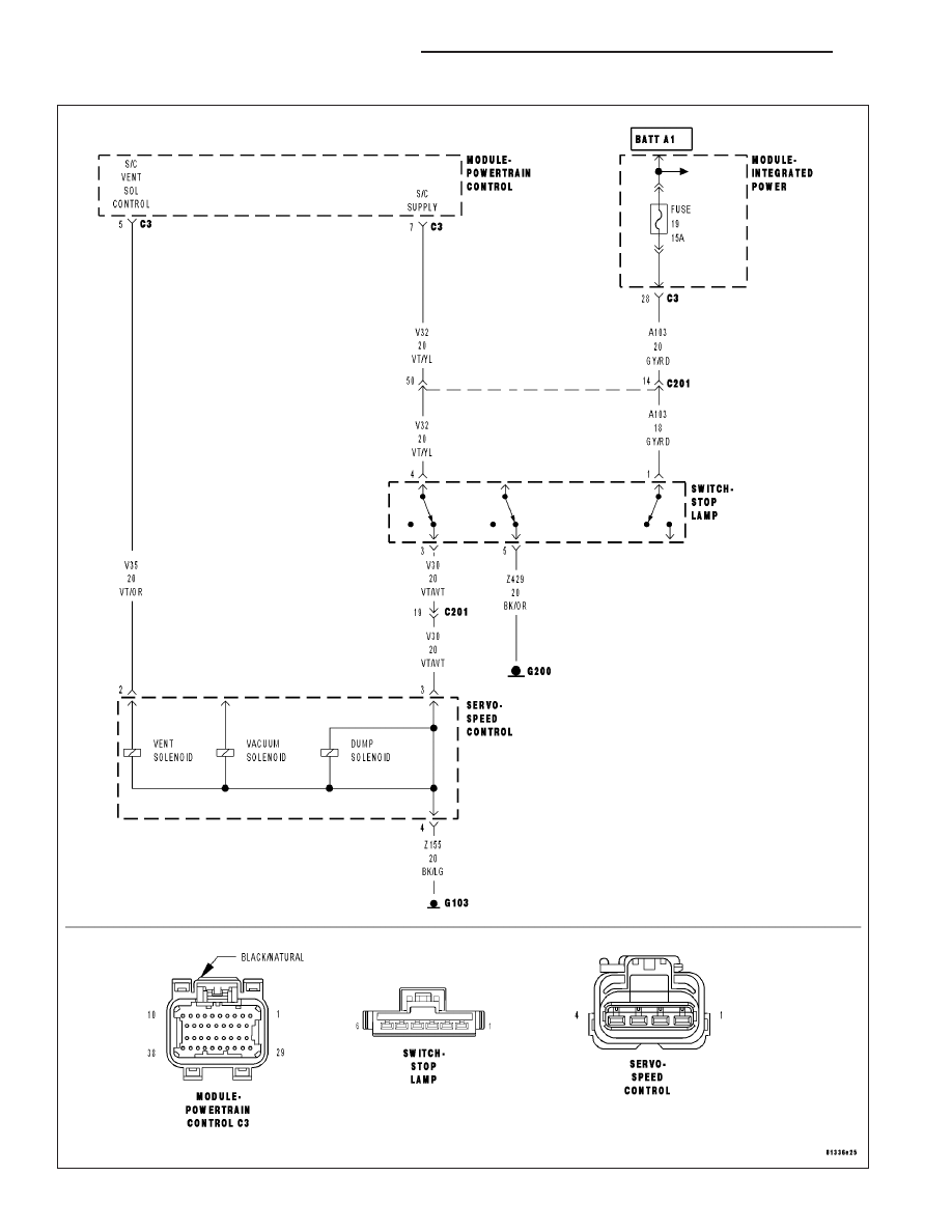
P0586-SPEED CONTROL VENT CONTROL CIRCUIT
9 - 558
ENGINE ELECTRICAL DIAGNOSTICS
ND