Index Dodge Dodge Dakota (ND) 2005 - service repair manual 2005 year
Search
Content .. 716 717 718 719 ..
Dodge Dakota (ND). Manual - part 718
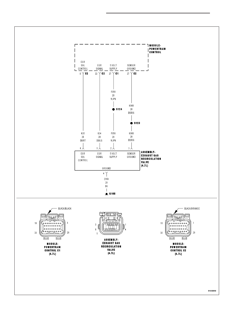
P0405-EGR POSITION SENSOR CIRCUIT LOW
9 - 410
ENGINE ELECTRICAL DIAGNOSTICS
ND