Dodge Dakota (ND). Manual - part 716
P0403-EGR SOLENOID CIRCUIT (CONTINUED)
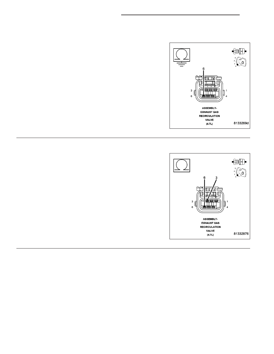
5.
(K35) EGR SOLENOID CONTROL CIRCUIT SHORTED TO GROUND
Turn the ignition off.
Measure the resistance between ground and the (K35) EGR Solenoid
Control circuit in the EGR Solenoid harness connector.
Is the resistance below 100 ohms?
Yes
>> Repair the short to ground in the (K35) EGR Solenoid
Control circuit.
Perform POWERTRAIN VERIFICATION TEST. (Refer to 9
- ENGINE - STANDARD PROCEDURE)
No
>> Go To 6
6.
(K35) EGR SOLENOID CONTROL CIRCUIT SHORTED TO THE (K900) SENSOR GROUND CIRCUIT
Measure the resistance between the (K35) EGR Solenoid Control cir-
cuit and the (K900) Sensor ground circuit in the EGR Solenoid con-
nector.
Is the resistance below 5.0 ohms?
Yes
>> Repair the short between the (K900) Sensor ground circuit
and the (K35) EGR Solenoid Control circuit.
Perform POWERTRAIN VERIFICATION TEST. (Refer to 9
- ENGINE - STANDARD PROCEDURE)
No
>> Go To 7
9 - 402
ENGINE ELECTRICAL DIAGNOSTICS
ND