Dodge Dakota (ND). Manual - part 246
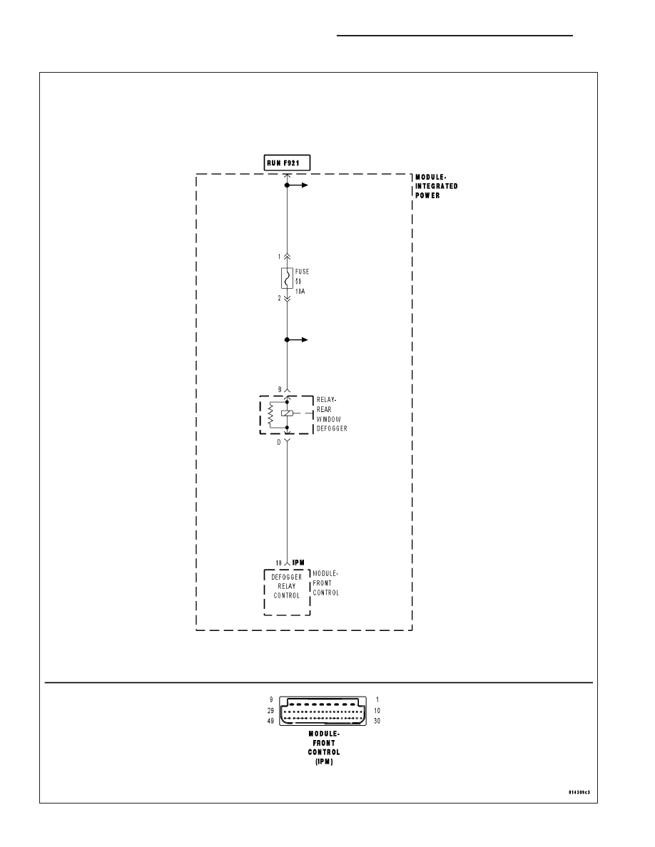
B106B,B106D–REAR DEFROST CONTROL CIRCUIT LOW/OPEN – FCM
8G - 2
HEATED GLASS - ELECTRICAL DIAGNOSTICS
ND
|
|
|
B106B,B106D–REAR DEFROST CONTROL CIRCUIT LOW/OPEN – FCM 8G - 2 HEATED GLASS - ELECTRICAL DIAGNOSTICS ND |