Index Dodge Dodge Dakota (ND) 2005 - service repair manual 2005 year
Search
Content .. 245 246 247 248 ..
Dodge Dakota (ND). Manual - part 247
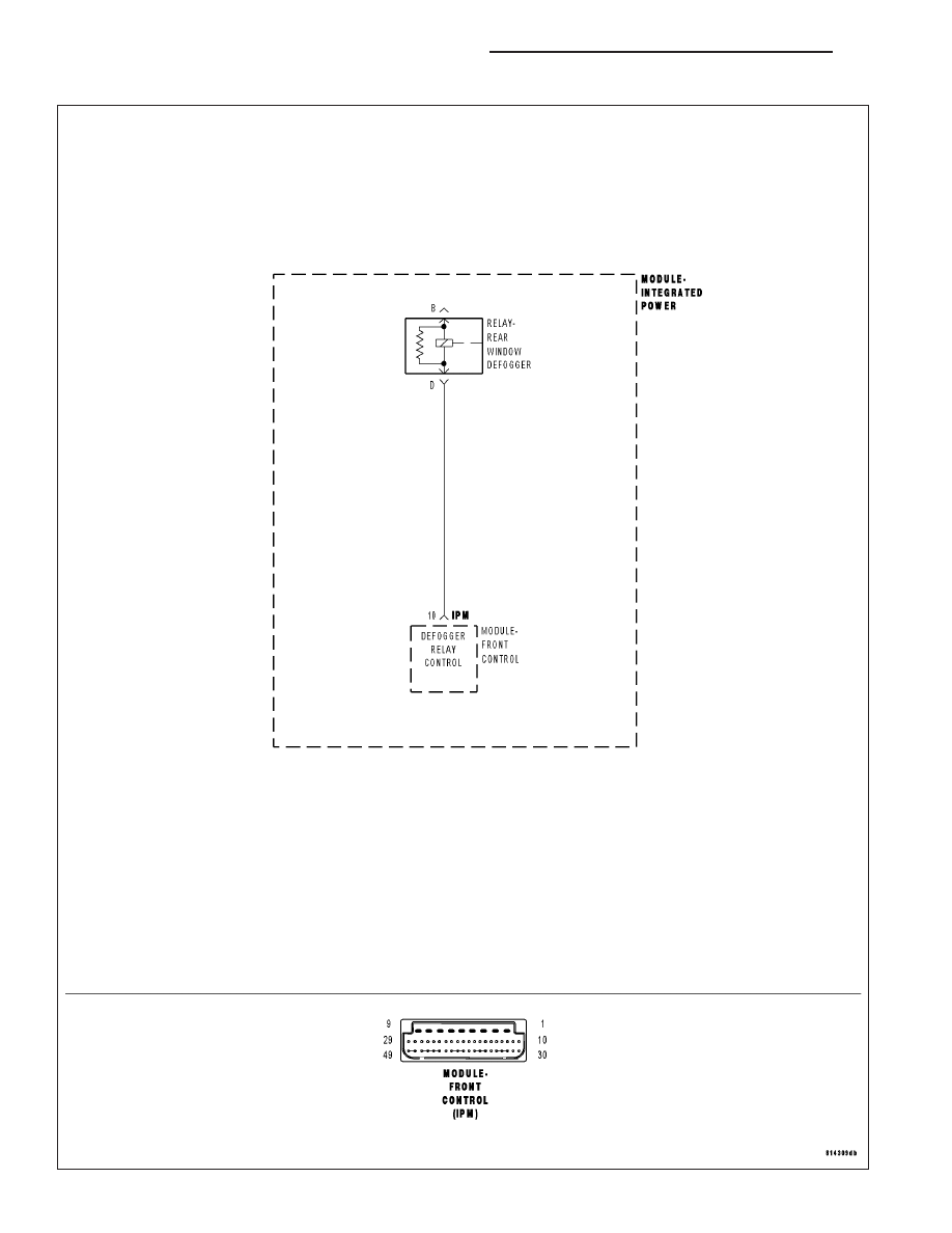
B106C–REAR DEFROST CONTROL CIRCUIT HIGH – FCM
8G - 6
HEATED GLASS - ELECTRICAL DIAGNOSTICS
ND