Content .. 1176 1177 1178 1179 ..
Dodge Dakota (ND). Manual - part 1178
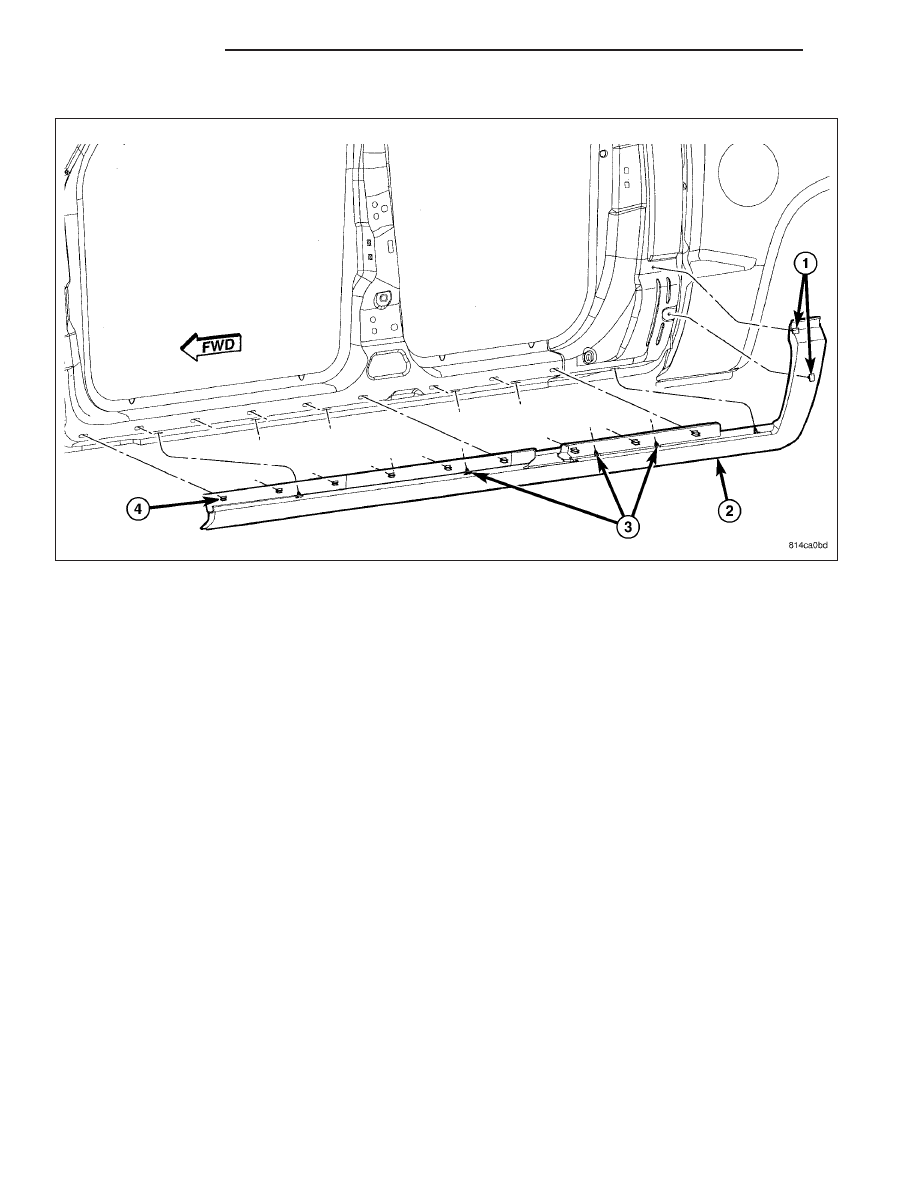
BODYSIDE CLADDING
1. Position the bodyside cladding (2) in the door opening(s) and install the fasteners (3).
2. Install the two fasteners holding the rear (1) of the bodyside cladding (2) to the rear side of the cab, just behind
the c-pillar.
23 - 124
EXTERIOR
ND