Dodge Dakota (ND). Manual - part 63


  Index      Dodge     Dodge Dakota (ND) 2005 - service repair manual 2005 year


Search            


Content   ..  61  62  63  64   ..


Dodge Dakota (ND). Manual - part 63


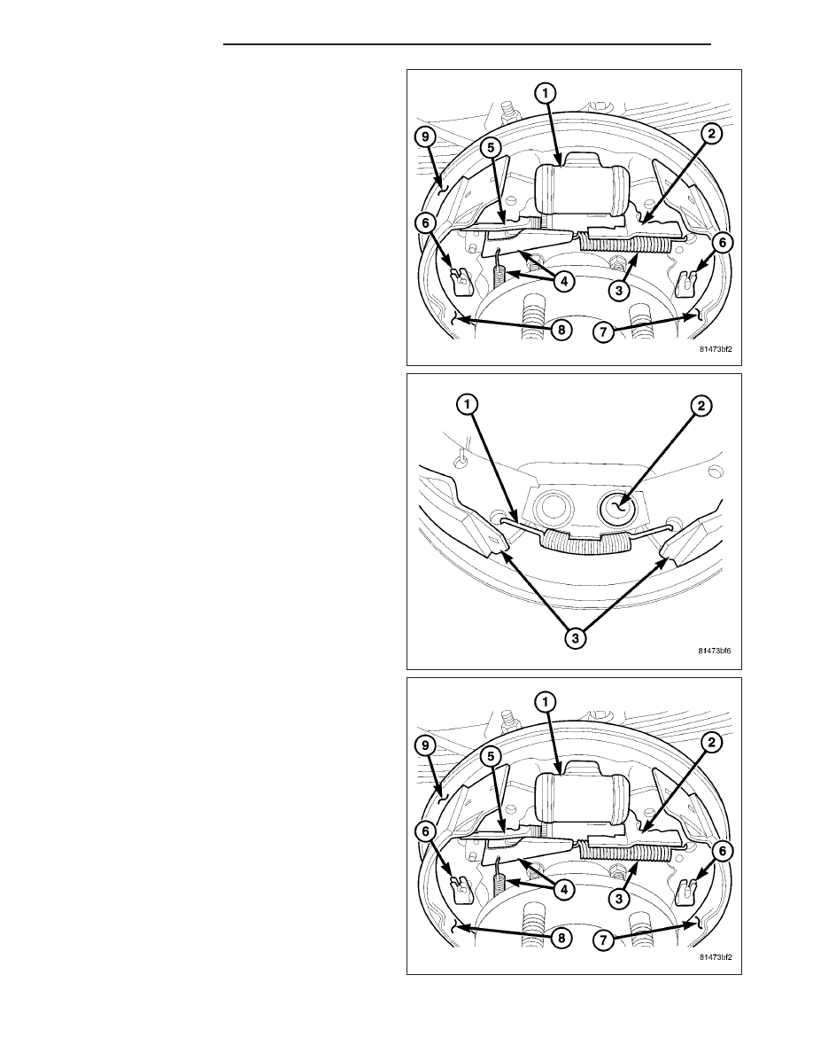
4. Install parking brake lever (2) to the rear shoe (7)

and install the hold down clip (6).

5. Install the adjuster strut (5) onto the shoes and

park brake lever (2).

6. Install the front shoe (8) on support plate (9). and

install the hold down clip (6).

7. Install the adjuster spring and lever (4) in the slot in

the adjuster strut (7).

8. Install the lower return spring (1) to the shoes (3).

9. Verify adjuster operation. Pull both shoes outward

to move the adjuster lever (4) to rotate the star
wheel. Be sure adjuster lever properly engages
star wheel teeth.

10. Adjust brake shoes to drum with brake gauge.

11. Install wheel and tire assembly. (Refer to 22 -

TIRES/WHEELS/WHEELS

-

STANDARD

PROCEDURE).

5 - 22

BRAKES - BASE

ND

ADJUSTMENTS - REAR DRUM BRAKE

The rear drum brakes are equipped with a self-adjusting mechanism. Under normal circumstances, the only time
adjustment is required is when the shoes are replaced, removed for access to other parts, or when one or both
drums are replaced.

Adjustment can be made with a standard brake gauge or with adjusting tool. Adjustment is performed with the com-
plete brake assembly installed on the backing plate.

ADJUSTMENT WITH BRAKE GAUGE

1. Be sure parking brakes are fully released.

2. Raise rear of vehicle and remove wheels and brake drums.

3. Verify that left and right automatic adjuster levers and cables are properly connected.

4. Insert brake gauge in drum. Expand gauge until gauge inner legs contact drum braking surface. Then lock gauge

in position.

5. Reverse gauge and install it on brake shoes. Posi-

tion gauge legs at shoe centers as shown. If gauge
does not fit (too loose/too tight), adjust shoes.

6. Pull shoe adjuster lever away from adjuster screw

star wheel.

7. Turn adjuster screw star wheel (by hand) to expand

or retract brake shoes. Continue adjustment until
gauge outside legs are light drag-fit on shoes.

8. Install brake drums and wheels and lower vehicle.

9. Drive vehicle and make 8-10 forward stops to oper-

ate automatic adjusters and equalize adjustment.

NOTE: Bring vehicle to complete standstill at each
stop. Incomplete, rolling stops will not activate
automatic adjusters.

ADJUSTMENT WITH ADJUSTING TOOL

1. Be sure parking brake lever is fully released.

2. Raise vehicle so rear wheels can be rotated freely.

3. Remove plug from each access hole in brake sup-

port plates.

4. Loosen parking brake cable adjustment nut until

there is slack in front cable.

5. Insert adjusting tool through support plate access

hole and engage tool in teeth of adjusting screw
star wheel.

ND

BRAKES - BASE

5 - 23

6. Rotate adjuster screw star wheel (move tool handle

upward) until slight drag can be felt when wheel is
rotated.

7. Push and hold adjuster lever away from star wheel

with thin screwdriver.

8. Back off adjuster screw star wheel until brake drag

is eliminated.

9. Repeat adjustment at opposite wheel. Be sure

adjustment is equal at both wheels.

10. Install support plate access hole plugs.

11. Adjust parking brake cable and lower vehicle.

12. Drive vehicle and make 8-10 forward stops to

operate automatic adjusters and equalize adjust-
ment.

NOTE: Bring vehicle to complete standstill at each
stop. Incomplete, rolling stops will not activate automatic adjusters.

DISC BRAKE CALIPERS

DESCRIPTION

NOTE: Petroleum based grease should not be used on any of the rubber components of the caliper, Use
only Non-Petroleum based grease.

The calipers are a dual piston type. The calipers are
free to slide laterally, this allows continuous compen-
sation for lining wear.

5 - 24

BRAKES - BASE

ND

OPERATION

When the brakes are applied fluid pressure is exerted
against the caliper piston (2). The fluid pressure is
exerted equally and in all directions. This means pres-
sure exerted against the caliper piston and within the
caliper bore will be equal.

Fluid pressure applied to the piston is transmitted
directly to the inboard brake pad (5). This forces the
pad lining against the inner surface of the disc brake
rotor. At the same time, fluid pressure within the piston
bore forces the caliper to slide inward on the mounting
bolts. This action brings the outboard brake pad lining
(6) into contact with the outer surface of the disc
brake rotor.

In summary, fluid pressure acting simultaneously on
both piston and caliper, produces a strong clamping
action. When sufficient force is applied, friction will
attempt to stop the rotors from turning and bring the vehicle to a stop.

Application and release of the brake pedal generates only a very slight movement of the caliper and piston. Upon
release of the pedal, the caliper and piston return to a rest position. The brake pads do not retract an appreciable
distance from the rotor. In fact, clearance is usually at, or close to zero. The reasons for this are to keep road debris
from getting between the rotor and lining and in wiping the rotor surface clear each revolution.

The caliper piston seal (4) controls the amount of piston (2) extension needed to compensate for normal lining wear.

During brake application, the seal is deflected outward
by fluid pressure and piston movement(6). When the
brakes (and fluid pressure) are released, the seal
relaxes and retracts the piston (3).

The amount of piston retraction is determined by the
amount of seal deflection. Generally the amount is just
enough to maintain contact between the piston and
inboard brake pad.

ND

BRAKES - BASE

5 - 25


Content   ..  61  62  63  64   ..