Chrysler Le Baron, Dodge Dynasty, Plymouth Acclaim. Manual - part 268


  Index      Dodge     Chrysler Le Baron, Dodge Dynasty, Plymouth Acclaim - service repair manual 1993 year


Search            


Content   ..  266  267  268  269   ..


Chrysler Le Baron, Dodge Dynasty, Plymouth Acclaim. Manual - part 268


It is important when using the Test Indicator that

the battery be level and have a clean top to see the
correct indications. A light may be required to view
the Indicator.

WARNING: DO NOT USE OPEN FLAME NEAR BAT-
TERY BECAUSE OF EXPLOSIVE GASES AT FORM
ABOVE BATTERY.

STATE OF CHARGE TESTS

USING TEST INDICATOR

The built in test hydrometer (Figs. 3, 4 and 5) mea-

sures the specific gravity of the electrolyte. Specific
Gravity (SG) of the electrolyte will show state of
charge voltage. The test indicator WILL NOT show
cranking capacity of the battery. Refer to Battery
Load. Look into the sight glass (Figs. 4 and 5) and
note the color of the indicator (Fig. 5). Refer to the
following description of colors:
• GREEN = 75 to 100 degree state of charge

The battery is adequately charged for further test-

ing and may be returned to use. If the vehicle will
not crank for a maximum 15 seconds, refer to Bat-
tery Load Test in this Group for more information.
• BLACK OR DARK = 0 to 75 degree state of
charge

The battery is INADEQUATELY charged and

must be charged until green dot is visible, (12.4 volts
or greater) before the battery is tested or returned to
use. Refer to Causes of Battery Discharging.
• YELLOW OR BRIGHT COLOR = Battery must
be replace

WARNING: DO NOT CHARGE, ASSIST BOOST,
LOAD TEST, OR ADD WATER TO THE BATTERY
WHEN YELLOW OR BRIGHT COLOR DOT IS VISI-
BLE. PERSONAL INJURY MAY OCCUR.

A yellow or bright color dot shows electrolyte level

in battery is below the test indicator (Fig. 5). Water
cannot be added to a maintenance free battery. The
battery must be replaced. A low electrolyte level may
be caused by an over charging condition. Refer to
Generator Test Procedures on Vehicle.

CAUSES OF BATTERY DISCHARGING

It is normal to have a small 5 to 30 milliamperes

continuous electrical draw from the battery. This
draw will take place with the ignition in the OFF po-
sition, and the courtesy, dome, storage compart-
ments, and engine compartment lights OFF. The
continuous draw is due to various electronic features
or accessories that require electrical current with the
ignition OFF to function properly. When a vehicle is
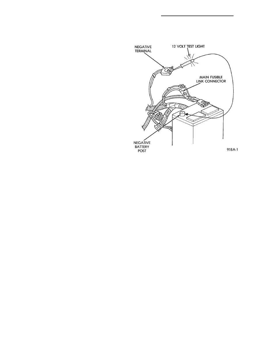
not used over an extended period approximately 20
days the Main Fusible Link Connector (Fig. 6)
should be disconnected. This is located near the bat-

tery on the engine wiring harness. Disconnection of
this connector will help prevent battery discharging.
Refer to Fig. 7 for Battery Diagnostics.

ABNORMAL BATTERY DISCHARGING

(1) Corroded battery posts, cables or terminals.
(2) Loose or worn generator drive belt.
(3) Electrical loads that exceed the output of the

charging system due to equipment or accessories in-
stalled after delivery.

(4) Slow driving speeds in heavy traffic conditions

or prolonged idling with high-amperage electrical
systems in use.

(5) Defective electrical circuit or component caus-

ing excess Ignition Off Draw (IOD). Refer to Ignition
OFF Draw (IOD).

(6) Defective charging system.
(7) Defective battery.

BATTERY OPEN CIRCUIT VOLTAGE TEST

An open circuit voltage, no load test will show the

state of charge in a battery. Also, if it will pass a
load test of 50 percent of the battery cold crank rat-
ing. Refer to Battery Load Test. If a battery has an
open circuit voltage reading of 12.4 volts or greater,
and will not pass a load test, it is defective and re-
placement would be required. To test open circuit
voltage, perform the following operation:

(1) Remove both battery cables, negative first. If

the battery has been boosted, charged, or loaded just
prior to this operation, allow the battery a few min-
utes to stabilize.

(2) Using a voltmeter connected to the battery

posts and measure the open circuit voltage (Fig. 8).

Fig. 6 Main Fusible Link Connector

8A - 4

BATTERY/STARTING/CHARGING SYSTEMS DIAGNOSTICS

Ä

Fig. 7 Battery Diagnostics

Ä

BATTERY/STARTING/CHARGING SYSTEMS DIAGNOSTICS

8A - 5

This voltage reading will show the battery state of

charge. It will not reveal battery cranking capacity
(Fig. 8).

BATTERY LOAD TEST

A fully charged battery must have reserve crank-

ing capacity. This will enable the starter motor and
ignition system enough power to start the engine
over a broad range of ambient temperatures. A bat-
tery load test will verify the actual cranking perfor-
mance based on the cold crank rating of the battery.

WARNING: IF BATTERY SHOWS SIGNS OF FREEZ-
ING, LEAKING, LOOSE POSTS, OR EXCESSIVELY
LOW ELECTROLYTE LEVEL, DO NOT TEST. ACID
BURNS OR AN EXPLOSIVE CONDITION MAY RE-
SULT.

(1) Remove both battery cables, negative first. Bat-

tery top, cables and posts should be clean. If green
dot is not visible in indicator, charge the battery. Re-
fer to Battery Charging Procedures.

(2) Use a suitable Volt Ammeter Load tester (Fig.

10) connected to the battery posts (Fig. 11). Check
the open circuit voltage of the battery.

Voltage should be equal to or greater than 12.4

volts with the green dot visible in test indicator.

(3) Rotate the load control knob Carbon pile rheo-

stat to apply a 300 amp load. Apply this load for 15

seconds to remove the surface charge from the bat-
tery, and return the control knob to off (Fig. 12).

(4) Allow the battery to stabilize for 15 seconds,

and then verify open circuit voltage.

(5) Rotate the load control knob on the tester to

maintain 50 percent of the battery cold crank rating
for a minimum 15 seconds (Fig. 13).

Fig. 8 Testing Open Circuit Voltage

Fig. 9 Battery Open Circuit Voltage

Fig. 10 Volt-Ammeter-Load Tester

Fig. 11 Volt-Ammeter-Load Tester Connections

Fig. 12 Remove Surface Charge from Battery

8A - 6

BATTERY/STARTING/CHARGING SYSTEMS DIAGNOSTICS

Ä

After 15 seconds, record the loaded voltage reading

and return the load control to the off position.

(6) Voltage drop will vary according to battery

temperature at the time of the load test. Battery
temperature can be estimated by the temperature of
exposure over the preceding several hours. If the bat-
tery has been charged, boosted, or loaded a few min-
utes prior to the test, the battery would be slightly
warmer. Refer to Fig. 14 for proper loaded voltage
reading.

(7) If battery passes load test, it is in good condi-

tion and further tests are not necessary. If it fails
load test, it should be replaced.

BATTERY CHARGING

A battery is considered fully charged when it will

meet all the following requirements:
• It has an open circuit voltage charge of at least
12.4 volts (Fig. 9)
• It passes the 15 second load test (Fig. 14)

• The built in test indicator dot is GREEN (Fig. 5)

• The battery cannot be refilled with water. It must
be replaced

WARNING: DO NOT CHARGE A BATTERY THAT
HAS EXCESSIVELY LOW ELECTROLYTE LEVEL.
BATTERY MAY SPARK INTERNALLY AND EX-
PLODE.

EXPLOSIVE GASES FORM OVER THE BATTERY.

DO

NOT

SMOKE,

USE

FLAME,

OR

CREATE

SPARKS NEAR BATTERY.

DO NOT ASSIST BOOST OR CHARGE A FROZEN

BATTERY. BATTERY CASING MAY FRACTURE.

BATTERY ACID IS POISON, AND MAY CAUSE SE-

VERE BURNS AND THE BATTERY CONTAIN SUL-
FURIC ACID. AVOID CONTACT WITH SKIN, EYES,
OR CLOTHING. IN THE EVENT OF CONTACT,
FLUSH WITH WATER AND CALL PHYSICIAN IMME-
DIATELY. KEEP OUT OF REACH OF CHILDREN.

CAUTION: Disconnect the battery negative cable
first (Fig. 15) before charging battery to avoid dam-
age to electrical systems. Do not exceed 16.0 volts
while charging battery. Refer to the instructions
supplied with charging equipment

Battery electrolyte will bubble inside the battery

case while being charged properly. If the electrolyte
boils violently, or is discharged from the vent holes
while charging, immediately reduce charging rate or
turn off charger. Evaluate battery condition. Battery
damage may occur if charging is excessive.

Some battery chargers are equipped with polarity

sensing devices to protect the charger or battery from
being damaged if improperly connected. If the bat-
tery state of charge is too low for the polarity sensor
to detect, the sensor must be bypassed for charger to
operate. Refer to operating instructions provided
with battery charger being used.

CAUTION: Charge battery until test indicator ap-
pears green. Do not overcharge.

It may be necessary to jiggle the battery or vehicle

to bring the green dot (in the test indicator) into
view.

After the battery has been charged to 12.4 volts or

greater, perform a load test to decide cranking capac-

Fig. 13 Load 50 Percent Cold Crank Rating

Fig. 14 Load Test Temperature

Fig. 15 Disconnect Negative Battery Cable

Ä

BATTERY/STARTING/CHARGING SYSTEMS DIAGNOSTICS

8A - 7


Content   ..  266  267  268  269   ..