Chrysler Sebring, Stratus sedan, Sebring Convertible. Manual - part 740


  Index      Chrysler     Chrysler Sebring, Stratus sedan, Sebring Convertible - service repair manual 2001-2007 year


Search            


Content   ..  738  739  740  741   ..


Chrysler Sebring, Stratus sedan, Sebring Convertible. Manual - part 740


(2) Position the vehicle in a wind free work area.

This will aid in detecting small leaks.

(3) Bring the refrigerant system up to operating

temperature and pressure. This is done by allowing
the engine to run for five minutes with the A/C sys-
tem set to the following:

• Transmission in Park or Neutral with parking

brake set

• Engine idling

• Mode control set to the outside air position

• Blower control set to the high speed position

• A/C set to the ON position

• All windows open

CAUTION: A leak detector only designed for R-12
refrigerant will not detect leaks in a R-134a refriger-
ant system.

(4) Shut the vehicle Off and wait 2-7 minutes.

Then use an electronic leak detector that is designed
to detect R-134a refrigerant and search for leaks. Fit-
tings, lines or components that appear to be oily usu-
ally indicate a refrigerant leak. To inspect the A/C
evaporator for leaks, insert the leak detector probe
into the drain tube opening or an air outlet. A dye for
R-134a is available to aid in leak detection. Use only
DaimlerChrysler approved refrigerant dye.

STANDARD PROCEDURE

REFRIGERANT SYSTEM SERVICE EQUIPMENT

WARNING: Eye protection must be worn when ser-
vicing an A/C refrigerant system. Turn all valves off
(rotate clockwise) on the equipment being used
before connecting or disconnecting service equip-
ment

from

the

refrigerant

system.

Failure

to

observe these warnings may result in personal
injury or death.

WARNING: Refer to the applicable warnings and cau-
tions for this system before performing the following
operation (Refer to 24 - HEATING & AIR CONDITION-
ING/PLUMBING - WARNINGS) and (Refer to 24 - HEAT-
ING & AIR CONDITIONING/PLUMBING - CAUTIONS).
Failure to follow the warnings and cautions could
result in possible personal injury or death.

When servicing the A/C system, a R-134a refriger-

ant recovery/recycling/charging station that meets
SAE standard J2210 must be used (Fig. 1). Contact
an automotive service equipment supplier for refrig-
erant recovery/recycling/charging equipment. Refer to
the operating instructions supplied by the equipment
manufacturer for proper care and use of this equip-
ment.

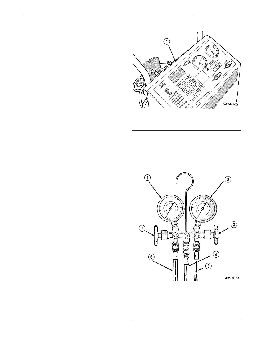
A manifold gauge set may be needed with some

recovery/recycling/charging equipment (Fig. 2). The
manifold gauge set should have manual shut-off
valves, or automatic back-flow valves located at the
service port connector end of the manifold gauge set
hoses. This will prevent refrigerant from being
released into the atmosphere.

Fig. 1 Refrigerant Recovery/Recycling Station -

Typical

1 - R-134 REFRIGERANT RECOVERY MACHINE

Fig. 2 Manifold Gauge Set - Typical

1 - LOW PRESSURE GAUGE
2 - HIGH PRESSURE GAUGE
3 - VALVE
4 - VACUUM/REFRIGERANT HOSE (YELLOW W/BLACK STRIP)
5 - HIGH PRESSURE HOSE (RED W/BLACK STRIP)
6 - LOW PRESSURE HOSE (BLUE W/BLACK STRIP)
7 - VALVE

JR

PLUMBING

24 - 59

PLUMBING (Continued)

MANIFOLD GAUGE SET CONNECTIONS

CAUTION: Do not use an R-12 manifold gauge set
on an R-134a system. The refrigerants are not com-
patible and system damage will result.

RECOVERY/RECYCLING/EVACUATION/

CHARGING HOSE – The center manifold hose (Yel-
low, or White, with Black stripe) is used to recover,
evacuate, and charge the refrigerant system. When
the low or high pressure valves on the manifold
gauge set are opened, the refrigerant in the system
will escape through this hose.

HIGH PRESSURE GAUGE HOSE – The high

pressure hose (Red with Black stripe) attaches to the
high side service port. This service port is located on
the receiver/drier near the engine coolant reservoir.
On this model, an A/C pressure transducer is also
used. A/C high-side pressures can be read using a
scan tool. Refer to 9 - Engine Electrical Diagnostics
for more information.

LOW PRESSURE GAUGE HOSE – The low

pressure hose (Blue with Black stripe) attaches to
the low side service port. This service port is located
on the suction line, near the right strut tower.

REFRIGERANT SYSTEM RECOVERY

WARNING: Refer to the applicable warnings and
cautions for this system before performing the fol-
lowing operation (Refer to 24 - HEATING & AIR
CONDITIONING/PLUMBING - WARNINGS) and (Refer
to 24 - HEATING & AIR CONDITIONING/PLUMBING -
CAUTIONS). Failure to follow the warnings and cau-
tions could result in possible personal injury or
death.

A R-134a refrigerant recovery/recycling/charging

station that meets SAE Standard J2210 must be
used to recover the refrigerant from an R-134a refrig-
erant system (Fig. 3). Refer to the operating instruc-
tions supplied by the equipment manufacturer for
the proper care and use of this equipment.

REFRIGERANT SYSTEM EVACUATE

NOTE: Special effort must be used to prevent mois-
ture from entering the A/C system oil. Moisture in
the oil is very difficult to remove and will cause a
reliability problem with the A/C compressor.

If an A/C compressor designed to use R-134a refrig-

erant is left open to the atmosphere for an extended
period of time. It is recommended that the refriger-
ant oil be drained and replaced with new oil or a new
A/C compressor be used. This will eliminate the pos-
sibility of contaminating the refrigerant system.

If the refrigerant system has been open to the

atmosphere, it must be evacuated before the refriger-
ant system can be filled. Moisture and air mixed
with the refrigerant system will raise the compressor
head pressure above acceptable operating levels. This
will reduce the performance of the A/C system and
damage the A/C compressor. Moisture will boil at
near room temperature when exposed to vacuum. A
R-134a refrigerant recovery/recycling/charging sta-
tion that meets SAE Standard J2210 must be used to
evacuate the refrigerant system. See the operating
instructions supplied by the equipment manufacturer
for proper care and use of this equipment. To evacu-
ate the refrigerant system, use the following proce-
dure:

NOTE: When connecting the service equipment
couplings to the refrigerant system service ports,
be certain that the valve of each coupling is fully
closed. This will reduce the amount of effort
required to make the connection.

(1) Connect a suitable charging station, refrigerant

recovery machine or a manifold gauge set with vac-
uum

pump

and

refrigerant

recovery

equipment

(Refer to 24 - HEATING & AIR CONDITIONING/
PLUMBING - STANDARD PROCEDURE - REFRIG-
ERANT SYSTEM SERVICE EQUIPMENT).

(2) Recover the refrigerant system (Refer to 24 -

HEATING & AIR CONDITIONING/PLUMBING -
STANDARD PROCEDURE - REFRIGERANT SYS-
TEM RECOVERY).

(3) Open the suction and discharge valves and

start the vacuum pump. The vacuum pump should
run a minimum of 45 minutes prior to charge to
eliminate all moisture within the refrigerant system.
When the suction gauge reads -88 kPa (-26 in. Hg)

Fig. 3 Refrigerant Recovery/Recycling Station -

Typical

1 - REFRIGERANT RECOVERY/RECYCLING STATION

24 - 60

PLUMBING

JR

PLUMBING (Continued)

vacuum or greater for 30 minutes, close all valves
and turn off vacuum pump. If the refrigerant system
fails to reach the specified vacuum, the refrigerant
system likely has a leak that must be corrected. If
the refrigerant system maintains specified vacuum
for at least 30 minutes, start the vacuum pump, open
the suction and discharge valves. Then allow the sys-
tem to evacuate an additional 10 minutes.

(4) Close all valves. Turn off and disconnect the

vacuum pump.

(5) Charge the refrigerant system (Refer to 24 -

HEATING & AIR CONDITIONING/PLUMBING -
STANDARD PROCEDURE - REFRIGERANT SYS-
TEM CHARGE).

REFRIGERANT SYSTEM CHARGE

WARNING: Refer to the applicable warnings and
cautions for this system before performing the fol-
lowing operation (Refer to 24 - HEATING & AIR
CONDITIONING/PLUMBING - WARNINGS) and (Refer
to 24 - HEATING & AIR CONDITIONING/PLUMBING -
CAUTIONS). Failure to follow the warnings and cau-
tions could result in possible personal injury or
death.

NOTE: Always refer to the underhood HVAC Speci-
fication Label for the refrigerant fill specification of
the vehicle being serviced.

After all refrigerant system leaks have been

repaired and the refrigerant system has been evacu-
ated, a refrigerant charge can be injected into the
system. For the proper amount of the refrigerant
charge, refer to the underhood HVAC Specification
Label.

A R-134a refrigerant recovery/recycling/charging

station that meets SAE Standard J2210 must be
used to charge the refrigerant system with R-134a
refrigerant. Refer to the operating instructions sup-
plied by the equipment manufacturer for proper care
and use of this equipment.

CHARGING PROCEDURE

CAUTION: A small amount of refrigerant oil is
removed from the A/C system each time the refrig-
erant system is recovered and evacuated. Before
charging the A/C system, you MUST replenish any
oil lost during the recovery process. Refer the
equipment manufacturer instructions for more infor-
mation.

(1) Evacuate the refrigerant system (Refer to 24 -

HEATING & AIR CONDITIONING/PLUMBING -

STANDARD PROCEDURE - REFRIGERANT SYS-
TEM EVACUATE).

(2) A manifold gauge set and an R-134a refriger-

ant recovery/recycling/charging station that meets
SAE standard J2210 should be connected to the
refrigerant system.

(3) Measure the proper amount of refrigerant and

heat it to 52° C (125° F) with the charging station.
See the operating instructions supplied by the equip-
ment manufacturer for proper use of this equipment.

(4) Open both the suction and discharge valves,

then open the charge valve to allow the heated
refrigerant to flow into the system.

(5) When the transfer of refrigerant has stopped,

close both the suction and discharge valves.

(6) If all of the refrigerant charge did not transfer

from the dispensing device, open all of the windows
in the vehicle and set the heating-A/C system con-
trols so that the A/C compressor is engaged and the
blower motor is operating at its lowest speed setting.
Run the engine at a steady high idle (about 1400
rpm). If the A/C compressor does not engage, test the
compressor clutch control circuit and repair as
required.

(7) Open the low-side valve to allow the remaining

refrigerant to transfer to the refrigerant system.

WARNING: Take care not to open the discharge
(high pressure) valve at this time. Failure to follow
this warning could result in possible personal injury
or death.

(8) Disconnect the charging station and manifold

gauge set from the refrigerant system service ports.

(9) Reinstall the caps onto the refrigerant system

service ports.

A/C COMPRESSOR

DESCRIPTION

A/C COMPRESSOR

Vehicles equipped with the 2.0 L and 2.4L Turbo

engine use the Sanden TRS - 090 A/C compressor.
Vehicles equipped with the 2.4L NA and 2.7L engines
use the Visteon HS-15 A/C compressor.

Both A/C compressors are fixed displacement type

compressors and use a high pressure relief valve to
protect the A/C system from excessive refrigerant
pressures. The Sanden TRS - 090 A/C compressor
uses an integral thermal limiter switch to protect it
from overheating and the HS-15 A/C compressor has
a replaceable compressor manifold which contains
the fittings for the refrigerant lines and the high
pressure relief valve.

JR

PLUMBING

24 - 61

PLUMBING (Continued)

CAUTION: The refrigerant oil in the R-134a A/C sys-
tem is unique depending on the A/C compressor
used. Use only PAG oils that are designed to work
with R-134a refrigerant and the A/C compressor in
the vehicle. Always refer to the underhood A/C Sys-
tem Specification Label for the correct oil designa-
tion.

Both A/C systems uses polyalkylene glycol syn-

thetic wax-free refrigerant oil PAG (refer to the
underhood A/C system label for the correct oil type
for the A/C compressor used in the system (depend-
ing on engine application).

HIGH PRESSURE RELIEF VALVE

A mechanical high pressure relief valve is used to

vent refrigerant from the A/C system to protect
against damage to the A/C compressor and other A/C
system components, caused by condenser air flow
restriction or an overcharge of refrigerant.

On the TRS-090 A/C compressor, the relief valve is

located on the compressor cylinder head, which is on
the rear of the compressor. On the HS-15 A/C com-
pressor, the relief valve is located on the replaceable
compressor manifold.

OPERATION

A/C COMPRESSOR

The A/C compressor is driven by the engine

through an electric clutch, drive pulley and belt
arrangement. The A/C compressor is lubricated by
refrigerant oil that is circulated throughout the
refrigerant system with the refrigerant.

The A/C compressor draws in low-pressure refrig-

erant vapor from the A/C evaporator through its suc-
tion port. It then compresses the refrigerant into a
high-pressure, high-temperature refrigerant vapor.
The A/C compressor pumps the high-pressure refrig-
erant vapor to the A/C condenser through the com-
pressor discharge port.

The A/C compressor cannot be repaired and, if

faulty or damaged, the entire compressor assembly
must be replaced. The compressor clutch, pulley and
clutch coil are available for service.

HIGH PRESSURE RELIEF VALVE

The high pressure relief valve vents refrigerant

from the A/C system when a discharge pressure of
3445 to 4135 kPa (500 to 600 psi) or above is
reached. The relief valve closes when a minimum dis-
charge pressure of 2756 kPa (400 psi) is reached.

The high pressure relief valve vents only enough

refrigerant to reduce the system pressure, and then
re-seats itself. The majority of the refrigerant is con-
served in the A/C system. If the relief valve vents

refrigerant, it does not necessarly mean that the
valve is faulty.

The high pressure relief valve is a factory-cali-

brated unit. The relief valve cannot be adjusted or
repaired, and must not be removed or otherwise dis-
turbed. On the TRS-090 A/C compressor, the relief
valve is serviced only as a part of the compressor
assembly. On the HS-15 A/C compressor, the relief
valve is serviced as a part of the compressor mani-
fold.

DIAGNOSIS AND TESTING

A/C COMPRESSOR NOISE

When investigating an A/C system related noise,

you must first know the conditions under which the
noise occurs. These conditions include: weather, vehi-
cle speed, transmission in gear or neutral, engine
speed, engine temperature, and any other special
conditions. Noises that develop during A/C operation
can often be misleading. For example: What sounds
like a failed front main bearing or connecting rod,
may be caused by loose bolts, nuts, mounting brack-
ets, or a loose A/C clutch assembly.

NOTE: Prior to a vehicle being removed from ser-
vice or stored for more than two weeks, the A/C
compressor should be operated to ensure adequate
refrigerant oil distribution throughout the system
components. Turn on the A/C for a minimum of five
minutes with outside air and the highest blower
speed selected.

Drive belts are speed sensitive. At different engine

speeds and depending upon belt tension, belts can
develop noises that are mistaken for an A/C compres-
sor noise. Improper belt tension can cause a mislead-
ing noise when the A/C clutch is engaged, which may
not occur when the A/C clutch is disengaged. Check
the accessory drive belt condition and tension as
described in Cooling before beginning this procedure.

(1) Select a quiet area for testing. Duplicate the

complaint conditions as much as possible. Switch the
A/C compressor on and off several times to clearly
identify the compressor noise. Listen to the A/C com-
pressor while the clutch is engaged and disengaged.
Probe the A/C compressor with an engine stethoscope
or a long screwdriver with the handle held to your
ear to better localize the source of the noise.

(2) Loosen all of the compressor mounting hard-

ware and retighten. Tighten the A/C clutch mounting
bolt. Be certain that the clutch field coil is mounted
securely to the A/C compressor, and that the clutch
plate and pulley are properly aligned and have the
correct air gap (Refer to 24 - HEATING & AIR CON-

24 - 62

PLUMBING

JR

A/C COMPRESSOR (Continued)


Content   ..  738  739  740  741   ..