Chrysler Sebring, Stratus sedan, Sebring Convertible. Manual - part 738


  Index      Chrysler     Chrysler Sebring, Stratus sedan, Sebring Convertible - service repair manual 2001-2007 year


Search            


Content   ..  736  737  738  739   ..


Chrysler Sebring, Stratus sedan, Sebring Convertible. Manual - part 738


(12) Position the floor distribution duct to the bot-

tom half of the HVAC housing (Fig. 33).

(13) Install the screws that secure the floor distri-

bution duct to the HVAC housing. Tighten the screws
to 2 N·m (17 in. lbs.).

NOTE: Make sure that the evaporator drain is clean
and unrestricted and that the evaporator insulator
is properly installed.

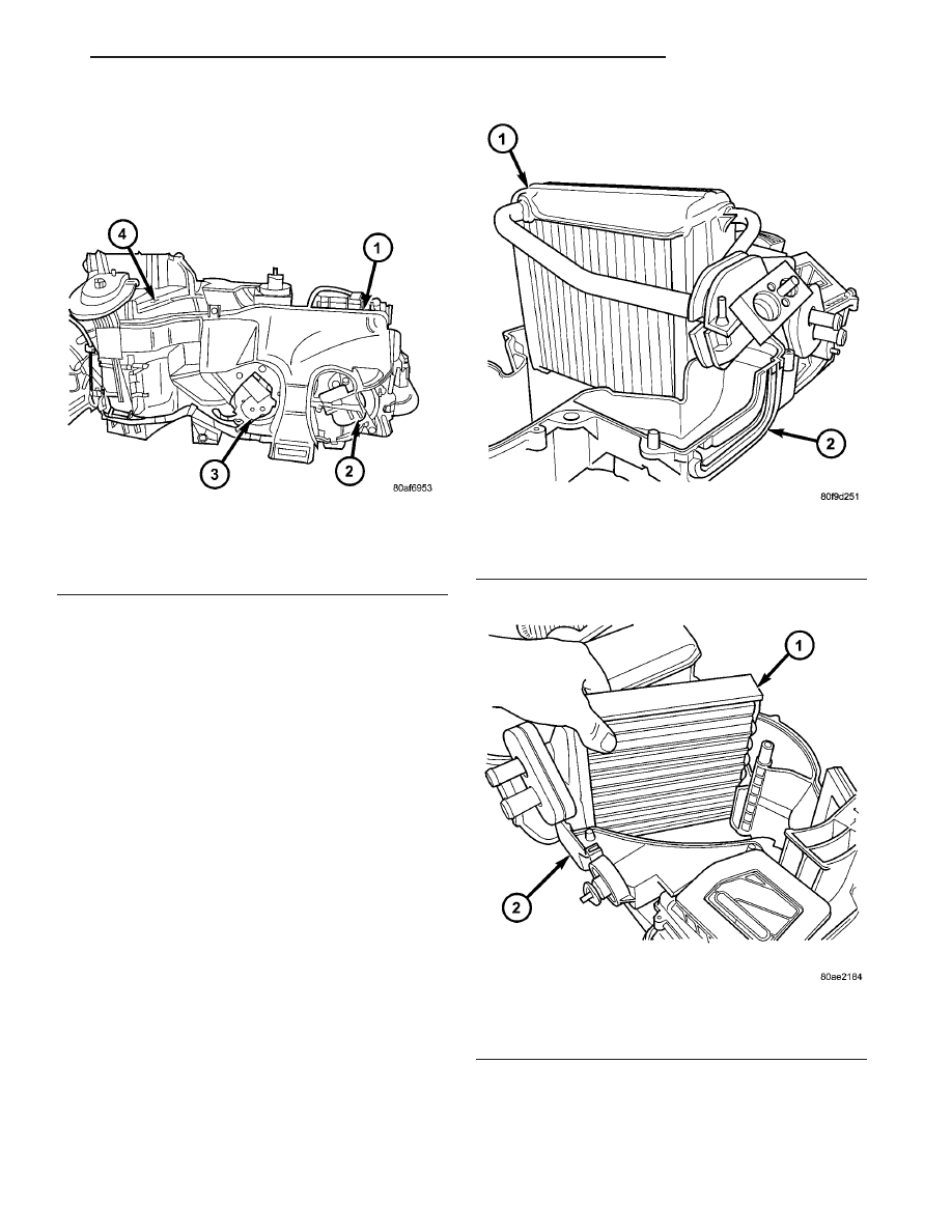
(14) Install the A/C evaporator into the bottom

half of the HVAC housing (Fig. 34).

NOTE: The A/C evaporator is manufactured with
three holes for evaporator temperature sensor
probe insertion. Always insert the probe into the
uppermost hole.

(15) Install the evaporator temperature sensor

probe into the A/C evaporator.

(16) Install the access plate to the HVAC housing.
(17) Install the heater core into the bottom half of

the HVAC housing (Fig. 35).

Fig. 33 Floor Distribution Duct

1 - FLOOR DISTRIBUTION DUCT
2 - MODE DOOR ACTUATOR
3 - BLEND DOOR ACTUATOR
4 - HVAC HOUSING

Fig. 34 A/C Evaporator

1 - A/C EVAPORATOR
2 - HVAC HOUSING (LOWER HALF)

Fig. 35 Heater Core

1 - HEATER CORE
2 - HVAC HOUSING (BOTTOM HALF)

JR

DISTRIBUTION

24 - 51

HVAC HOUSING (Continued)

(18) Align the blend and mode door shafts with the

holes in the HVAC housing and install the top half of
the housing to the bottom half of the housing (Fig.
36).

(19) Install the screws that secure the two halves

of the HVAC housing together. Tighten the screws to
2 N·m (17 in. lbs.).

(20) Install the foam seals on the heater core and

evaporator coil tube mounting flange (Fig. 37).

(21) Install the recirculation-air door into the air

inlet housing.

(22) Install the recirculation door gear onto the

recirculation door shaft (Fig. 38).

NOTE: The recirculation door actuator gear and
door gear must be properly aligned to operate cor-
rectly.

(23) Align and install the recirculation door actua-

tor gear with the door gear.

(24) Install the screw that secure the recirculation

door actuator gear to the air inlet housing. Tighten
the screw to 2 N·m (17 in. lbs.).

Fig. 36 Blend And Mode Door Shafts

1 - PANEL DOOR SHAFT
2 - BLEND DOOR SHAFT
3 - BLEND DOOR SHAFT

Fig. 37 HVAC Housing Seals

1 - EVAPORATOR SEAL
2 - A/C EXPANSION VALVE
3 - HVAC HOUSING
4 - HEATER CORE TUBES
5 - HVAC HOUSING STUD
6 - HVAC HOUSING STUD
7 - EXPANSION VALVE BOLT (2)

Fig. 38 Recirculation Door Actuator Gear

1 - DOOR GEAR
2 - ACTUATOR GEAR
3 - HVAC AIR INLET HOUSING

24 - 52

DISTRIBUTION

JR

HVAC HOUSING (Continued)

(25) Align the recirculation door actuator spline

with the spline in the recirculation door gear and
install the recirculation door actuator (Fig. 39).

(26) Install the three screws that secure the recir-

culation door actuator to the HVAC housing. Tighten
the screws to 2 N·m (17 in. lbs.).

(27) Install the air inlet housing onto the HVAC

housing.

(28) Install the screws that secure the air inlet

housing to the HVAC housing. Tighten the screws to
2 N·m (17 in. lbs.).

(29) If removed, install the blower motor resistor

or power module (depending on application). Install
and tighten the screws to 2 N·m (17 in. lbs.).

(30) If removed, install the blower motor. Install

and tighten the screws to 2 N·m (17 in. lbs.).

NOTE: Make sure that all HVAC wire harness leads
are routed through all HVAC housing wiring retain-
ers.

(31) Install the HVAC wire harness onto the HVAC

housing.

(32) Install the two screws that secure the HVAC

wire

harness

connector

to

the

HVAC

housing.

Tighten the screws to 2 N·m (17 in. lbs.).

(33) Connect the HVAC wire harness connectors to

the blower motor, blower motor resistor or power
module (depending on application), evaporator tem-
perature sensor and each actuator.

(34) Install the HVAC housing (Refer to 24 -

HEATING & AIR CONDITIONING/DISTRIBUTION/
HVAC HOUSING - INSTALLATION).

INSTALLATION

NOTE: The HVAC housing must be removed from
the vehicle and disassembled for service of the A/C
evaporator, heater core and the mode-air and blend-
air doors.

(1) Position the HVAC housing to the instrument

panel. Make sure that all air ducts are properly
aligned or connected.

(2) Install the two nuts and bolts that secure the

HVAC housing to the instrument panel. Tighten the
nuts and bolts securely.

(3) Connect the HVAC wire harness to the instru-

ment panel wire harness connector.

NOTE: Verify that the evaporator drain tube and
evaporator seals are properly seated to the HVAC
housing before installing the instrument panel and
HVAC Housing into the vehicle.

(4) Install the instrument panel and HVAC hous-

ing as an assembly (Refer to 23 - BODY/INSTRU-
MENT PANEL/INSTRUMENT PANEL ASSEMBLY -
INSTALLATION).

(5) Reconnect the negative battery cable.
(6) If the heater core is being replaced, flush the

cooling system (Refer to 7 - COOLING - STANDARD
PROCEDURE - COOLING SYSTEM CLEANING/
REVERSE FLUSHING).

(7) Refill the engine cooling system (Refer to 7 -

COOLING - STANDARD PROCEDURE - COOLING
SYSTEM REFILL).

(8) Evacuate the refrigerant system (Refer to 24 -

HEATING & AIR CONDITIONING/PLUMBING -
STANDARD PROCEDURE - REFRIGERANT SYS-
TEM EVACUATE).

(9) Charge the refrigerant system (Refer to 24 -

HEATING & AIR CONDITIONING/PLUMBING -
STANDARD PROCEDURE - REFRIGERANT SYS-
TEM CHARGE).

Fig. 39 Recirculation Door Actuator

1 - HVAC AIR INLET HOUSING
2 - RECIRCULATION DOOR ACTUATOR

JR

DISTRIBUTION

24 - 53

HVAC HOUSING (Continued)

INSTRUMENT PANEL DUCTS

REMOVAL

WARNING: On vehicles equipped with airbags, dis-
able the airbag system before attempting any steer-
ing wheel, steering column, or instrument panel
component diagnosis or service. Disconnect and
isolate the battery negative (ground) cable, then
wait two minutes for the airbag system capacitor to
discharge before performing further diagnosis or
service. This is the only sure way to disable the air-
bag system. Failure to take the proper precautions
could result in accidental airbag deployment and
possible personal injury or death.

(1) Remove the instrument panel and HVAC hous-

ing from the vehicle as an assembly and separate the
HVAC housing from the instrument panel (Refer to
23 - BODY/INSTRUMENT PANEL/INSTRUMENT
PANEL ASSEMBLY - REMOVAL).

(2) Remove the instrument panel top cover from

the instrument panel (Refer to 23 - BODY/INSTRU-
MENT PANEL/INSTRUMENT PANEL TOP COVER
- REMOVAL).

(3) Remove the defroster duct from the instrument

panel (Refer to 24 - HEATING & AIR CONDITION-
ING/DISTRIBUTION/DEFROSTER

DUCT

-

REMOVAL).

(4) Remove the speakers from the instrument

panel (Refer to 8 - ELECTRICAL/AUDIO/SPEAKER
- REMOVAL).

(5) If equipped, remove the sun sensor from the

instrument panel (Refer to 24 - HEATING & AIR
CONDITIONING/CONTROLS/SUN

SENSOR

-

REMOVAL).

(6) Remove the instrument cluster from the instru-

ment panel (Refer to 8 - ELECTRICAL/INSTRU-
MENT CLUSTER - REMOVAL).

(7) Remove the passenger side air bag from the

instrument panel (Refer to 8 - ELECTRICAL/RE-
STRAINTS/PASSENGER AIRBAG - REMOVAL).

(8) Remove the screws that secure the center dis-

tribution duct to the instrument panel support (Fig.
40).

(9) Remove the center distribution duct from the

instrument panel support and disconnect it from the
panel and demister duct assembly.

(10) Remove the center instrument panel duct

from the instrument panel

(11) Remove the screws that secure the panel and

demister duct assembly to the instrument panel sup-
port and remove the duct assembly.

INSTALLATION

(1) Install the panel and demister duct assembly

into the instrument panel.

(2) Install the screws that secure the panel and

demister duct assembly to the instrument panel sup-
port. Tighten the screws to 2 N·m (17 in. lbs.).

(3) Install the center instrument panel duct into

the instrument panel.

(4) Install the center distribution duct into the

instrument panel and connect it to the panel and
demister duct assembly.

(5) Install the screws that secure the center distri-

bution duct to the instrument panel support. Tighten
the screws to 2 N·m (17 in. lbs.).

(6) Install the passenger side air bag into the

instrument panel (Refer to 8 - ELECTRICAL/RE-
STRAINTS/PASSENGER

AIRBAG

-

INSTALLA-

TION).

(7) Install the instrument cluster into the instru-

ment panel (Refer to 8 - ELECTRICAL/INSTRU-
MENT CLUSTER - INSTALLATION).

(8) If equipped , install the sun sensor onto the

instrument panel (Refer to 24 - HEATING & AIR
CONDITIONING/CONTROLS/SUN

SENSOR

-

INSTALLATION).

(9) Install the speakers into the instrument panel

(Refer to 8 - ELECTRICAL/AUDIO/SPEAKER -
INSTALLATION).

(10) Install the defroster duct onto the instrument

panel (Refer to 24 - HEATING & AIR CONDITION-
ING/DISTRIBUTION/DEFROSTER

DUCTS

-

INSTALLATION).

Fig. 40 Instrument Panel Ducts - Removed

1 - PANEL AND DEMISTER DUCT ASSEMBLY
2 - CENTER PANEL DUCT
3 - CENTER DISTRIBUTION DUCT

24 - 54

DISTRIBUTION

JR


Content   ..  736  737  738  739   ..