Chrysler Sebring, Stratus sedan, Sebring Convertible. Manual - part 681


  Index      Chrysler     Chrysler Sebring, Stratus sedan, Sebring Convertible - service repair manual 2001-2007 year


Search            


Content   ..  679  680  681  682   ..


Chrysler Sebring, Stratus sedan, Sebring Convertible. Manual - part 681


(7) Install a hog ring at each hog ring locator to

hold upper horizontal seam wire to wire in seat back
foam.

(8) Install hog rings attaching seat cover seam

wires to seat frame.

(9) Pull seat cover over seat back frame and seat

back foam.

(10) Install hog rings at hog ring locators around

perimeter of seat back cushion attaching seat cover
to seat back frame.

(11) Install rear seat back to vehicle (Refer to 23 -

BODY/SEATS/REAR

SEAT

BACK

-

INSTALLA-

TION).

SEAT ADJUSTERS

REMOVAL

REMOVAL - FRONT SEAT ADJUSTER – POWER

(1) Remove front seat from vehicle.
(2) Remove seat cushion side shield and disconnect

switch connector.

(3) Remove seat back.
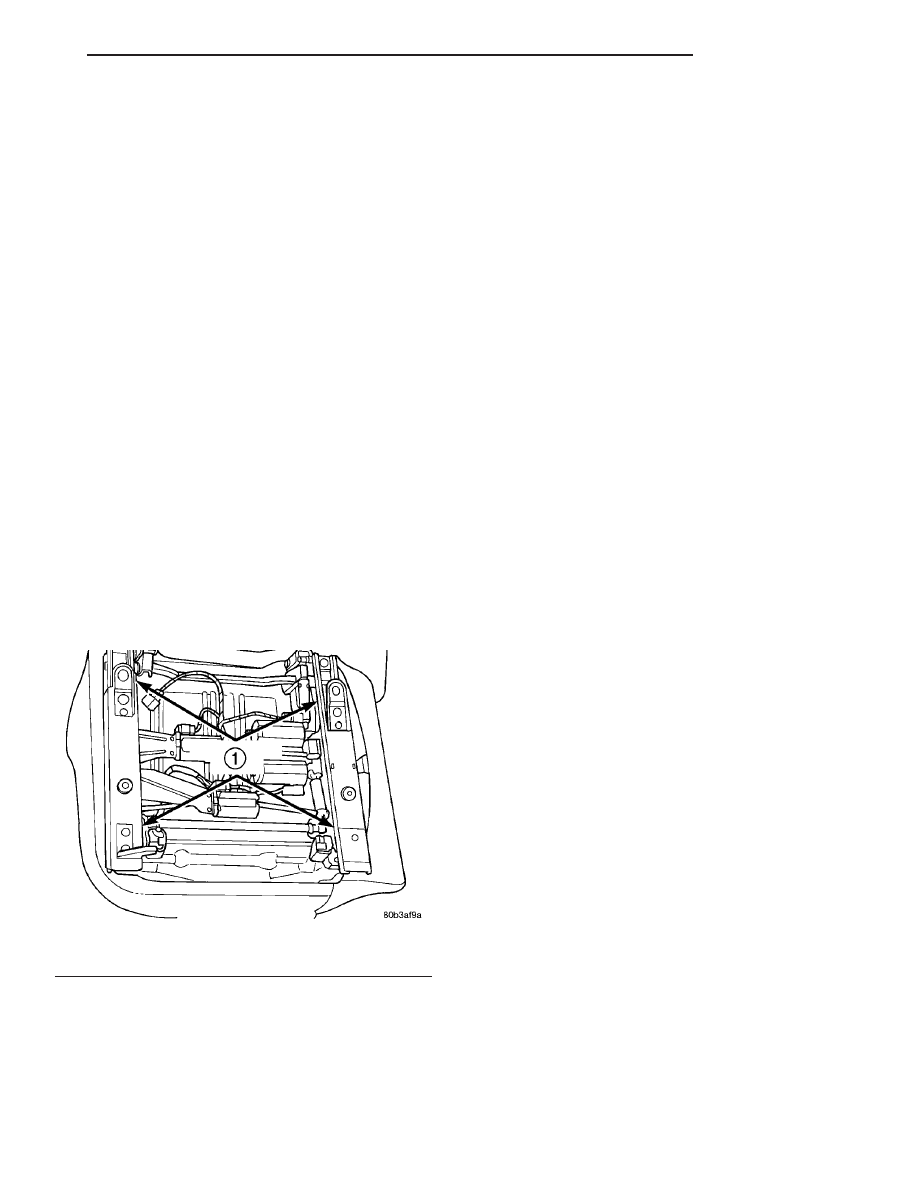
(4) Remove bolts attaching seat adjuster to cush-

ion pan (Fig. 33).

(5) Disconnect wire harness fasteners from cushion

pan.

(6) Remove seat adjuster from seat cushion.

REMOVAL - MANUAL ADJUSTER

(1) Remove front seat from vehicle (Refer to 23 -

BODY/SEATS/SEAT - REMOVAL).

(2) Remove recliner handle.
(3) Remove seat cushion side shield (Refer to 23 -

BODY/SEATS/SEAT CUSHION SIDE SHIELDS -
REMOVAL).

(4) Remove seat back (Refer to 23 - BODY/SEATS/

SEAT BACK - REMOVAL).

(5) Remove recliner.
(6) Remove towel bar spring.
(7) Remove push nuts attaching towel bar to seat

adjuster.

(8) Remove towel bar from seat adjuster.
(9) Remove seat adjuster.

INSTALLATION

INSTALLATION - FRONT SEAT ADJUSTER –
POWER

(1) Place seat adjuster in position on seat cushion

pan.

(2) Connect wire harness fasteners to the cushion

pan.

(3) Install bolts attaching seat adjuster to cushion

pad.

(4) Install seat back.
(5) Install bolt to attach seat back recliner to seat

back on each side of seat. Tighten bolt to 12 N·m (9
ft. lbs.) torque.

(6) Connect wire connectors and install the cush-

ion side shields.

(7) Install front seat in vehicle.

INSTALLATION - MANUAL ADJUSTER

(1) Place seat adjuster in position.
(2) Install seat adjuster.
(3) Install towel bar to seat adjuster.
(4) Install new push nuts to attach towel bar to

seat adjuster.

(5) Install towel bar spring.
(6) Install recliner.
(7) Install seat back (Refer to 23 - BODY/SEATS/

SEAT BACK - INSTALLATION).

(8) Install bolt to attach seat back recliner to seat

back on each side of seat. Tighten recliner bolt to 12
N·m (9 ft. lbs.) torque. Tighten pivot bolts to 40 N·m
(30 ft. lbs.) torque.

(9) Install recliner handle.
(10) Install front seat in vehicle (Refer to 23 -

BODY/SEATS/SEAT - INSTALLATION).

Fig. 33 Front Seat Track

1 - ATTACHING BOLTS

JR

SEATS

23 - 121

REAR SEAT BACK COVER (Continued)

SEAT BACK LATCH STRIKER

REMOVAL

(1) Release seat back latch and fold down.
(2) Remove the bolts and remove the latch striker

(Fig. 34).

INSTALLATION

NOTE: Striker is not symmetrical and should be
installed with the white date code towards the out-
side of the vehicle.

(1) Install the seat back striker and install the

bolts.

(2) Tighten the bolts to 12 N·m (9 ft. lbs.).
(3) Lock seat back in the up position and check for

operation.

SEAT BACK RECLINER

REMOVAL

REMOVAL

(1) Remove front seat from vehicle.
(2) Remove recliner handle
(3) Remove seat cushion side shield.
(4) Remove seat back.
(5) Remove manual recliner right and left bolts.
(6) Remove manual recliner assembly.

REMOVAL - JR-27 ONLY

(1) Remove seat from vehicle (Refer to 23 - BODY/

SEATS/SEAT - REMOVAL).

(2) Remove seat back from lower seat frame (Refer

to 23 - BODY/SEATS/SEAT BACK - REMOVAL).

(3) Remove upper recliner handle.
(4) Remove seat back cover until the screws

attaching the upper recliner mechanism to the seat
back frame can be accessed.

(5) Remove rubber bellows covering lower part of

seat back frame.

(6) Remove screws attaching upper recliner mech-

anism to seat frame.

(7) Remove bolts attaching recliner housing to seat

frame.

(8) Push upper recliner mechanism into seat frame

with handle shaft facing the front of the seat frame.

NOTE: Do not reuse bolts holding recliner housing
to seat frame. Verify availability prior to proceeding.

(9) Pull recliner housing and upper recliner handle

mechanism downward and out through bottom of
seat frame (Fig. 35).

INSTALLATION

INSTALLATION

(1) Place seat recliner in position.
(2) Install manual recliner right and left bolts.
(3) Install seat back.
(4) Install recliner.
(5) Install bolt to attach seat back recliner to seat

back on each side of seat. Tighten recliner bolt to 12
N·m (9 ft. lbs.) torque. Tighten pivot bolts to 40 N·m
(30 ft. lbs.) torque.

(6) Remove seat cushion side shield.
(7) Install recliner handle.
(8) Install front seat in vehicle.

Fig. 34 SEAT BACK STRIKER

1 - STRIKER
2 - BOLTS

Fig. 35 Recliner Housing

1 - UPPER RECLINER MECHANISM
2 - RECLINER HOUSING
3 - RECLINER CABLE

23 - 122

SEATS

JR

INSTALLATION - JR-27 ONLY

(1) Feed

upper

recliner

mechanism

and

then

recliner housing into the seat back frame with han-
dle shaft facing the front of the seat frame.

(2) Install new bolts to attach seat recliner hous-

ing to seat frame. Tighten to 34 N·m (300 in. lbs.)
torque.

(3) Pull upper recliner mechanism through hole in

seat frame.

(4) Install screws attaching upper recliner mecha-

nism to seat frame.

(5) Install rubber bellows covering lower part of

seat back frame.

(6) Install seat back cover.
(7) Install recliner spring bracket, spring, and lead

screw.

(8) Install seat back to lower seat frame (Refer to

23 - BODY/SEATS/SEAT BACK - INSTALLATION).

(9) Install recliner handle.
(10) Install seat into vehicle (Refer to 23 - BODY/

SEATS/SEAT - INSTALLATION).

JR

SEATS

23 - 123

SEAT BACK RECLINER (Continued)

STATIONARY GLASS

TABLE OF CONTENTS

page

page

WINDSHIELD

DESCRIPTION

. . . . . . . . . . . . . . . . . . . . . . . . 124

WARNING

WINDSHIELD SAFETY PRECAUTIONS

. . . . 124

REMOVAL

REMOVAL - JR-27 ONLY

. . . . . . . . . . . . . . . 124

REMOVAL

. . . . . . . . . . . . . . . . . . . . . . . . . . 125

INSTALLATION

INSTALLATION - JR-27

. . . . . . . . . . . . . . . . 126

INSTALLATION

. . . . . . . . . . . . . . . . . . . . . . 127

BACKLITE

REMOVAL

. . . . . . . . . . . . . . . . . . . . . . . . . . . . 128

INSTALLATION

. . . . . . . . . . . . . . . . . . . . . . . . 129

WINDSHIELD

DESCRIPTION

The windshield is attached to the window frame

with urethane adhesive. The urethane adhesive is
applied cold and seals the surface area between the
window opening and the glass. The primer adheres
the urethane adhesive to the windshield.

It is difficult to salvage a windshield during the

removal operation. The windshield is part of the
structural support for the roof. The urethane bonding
used to secure the windshield to the fence is difficult
to cut or clean from any surface. If the moldings are
set in urethane, it would also be unlikely they could
be salvaged. Before removing the windshield, check
the availability of the windshield and moldings from
the parts supplier.

WARNING

WINDSHIELD SAFETY PRECAUTIONS

WARNING:

DO

NOT

OPERATE

THE

VEHICLE

WITHIN 24 HOURS OF WINDSHIELD INSTALLATION.
IT TAKES AT LEAST 24 HOURS FOR URETHANE
ADHESIVE TO CURE. IF IT IS NOT CURED, THE
WINDSHIELD MAY NOT PERFORM PROPERLY IN
AN ACCIDENT.
URETHANE ADHESIVES ARE APPLIED AS A SYS-
TEM. USE GLASS CLEANER, GLASS PREP SOL-
VENT, GLASS PRIMER, PVC (VINYL) PRIMER AND
PINCH WELD (FENCE) PRIMER PROVIDED BY THE
ADHESIVE MANUFACTURER. IF NOT, STRUCTURAL
INTEGRITY COULD BE COMPROMISED.
DAIMLERCHRYSLER

DOES

NOT

RECOMMEND

GLASS

ADHESIVE

BY

BRAND.

TECHNICIANS

SHOULD REVIEW PRODUCT LABELS AND TECHNI-
CAL DATA SHEETS, AND USE ONLY ADHESIVES
THAT THEIR MANUFACTURES WARRANT WILL

RESTORE A VEHICLE TO THE REQUIREMENTS OF
FMVSS 212. TECHNICIANS SHOULD ALSO INSURE
THAT PRIMERS AND CLEANERS ARE COMPATIBLE
WITH THE PARTICULAR ADHESIVE USED.
BE SURE TO REFER TO THE URETHANE MANU-
FACTURER’S

DIRECTIONS

FOR

CURING

TIME

SPECIFICATIONS, AND DO NOT USE ADHESIVE
AFTER ITS EXPIRATION DATE.
VAPORS THAT ARE EMITTED FROM THE URE-
THANE ADHESIVE OR PRIMER COULD CAUSE
PERSONAL INJURY. USE THEM IN A WELL-VENTI-
LATED AREA.
SKIN

CONTACT

WITH

URETHANE

ADHESIVE

SHOULD BE AVOIDED. PERSONAL INJURY MAY
RESULT.
ALWAYS WEAR EYE AND HAND PROTECTION
WHEN WORKING WITH GLASS.

CAUTION: Protect all painted and trimmed surfaces
from coming in contact with urethane or primers.
Be careful not to damage painted surfaces when
removing moldings or cutting urethane around
windshield.

REMOVAL

REMOVAL - JR-27 ONLY

EXTERIOR METHOD

(1) Open convertible top.
(2) Remove

header/A-pilllar

weatherstrip

from

weatherstrip retainers.

(3) Remove A-pillar

weatherstrip

retainer

and

molding.

(4) Remove header weatherstrip/molding.
(5) Mark top edge of the windshield glass at three

locations on the header.

(6) Remove windshield wiper arms.
(7) Remove cowl cover.

23 - 124

STATIONARY GLASS

JR


Content   ..  679  680  681  682   ..