Chrysler Sebring, Stratus sedan, Sebring Convertible. Manual - part 663


  Index      Chrysler     Chrysler Sebring, Stratus sedan, Sebring Convertible - service repair manual 2001-2007 year


Search            


Content   ..  661  662  663  664   ..


Chrysler Sebring, Stratus sedan, Sebring Convertible. Manual - part 663


WATER DAM

REMOVAL

(1) Remove door trim panel. (Refer to 23 - BODY/

DOOR - FRONT/TRIM PANEL - REMOVAL)

(2) Remove door speaker, if equipped. (Refer to 8 -

ELECTRICAL/AUDIO/SPEAKER - REMOVAL)

CAUTION: Do not use dirty hands or lint type
gloves when removing the watershield, adhesive
bead will be ruined.

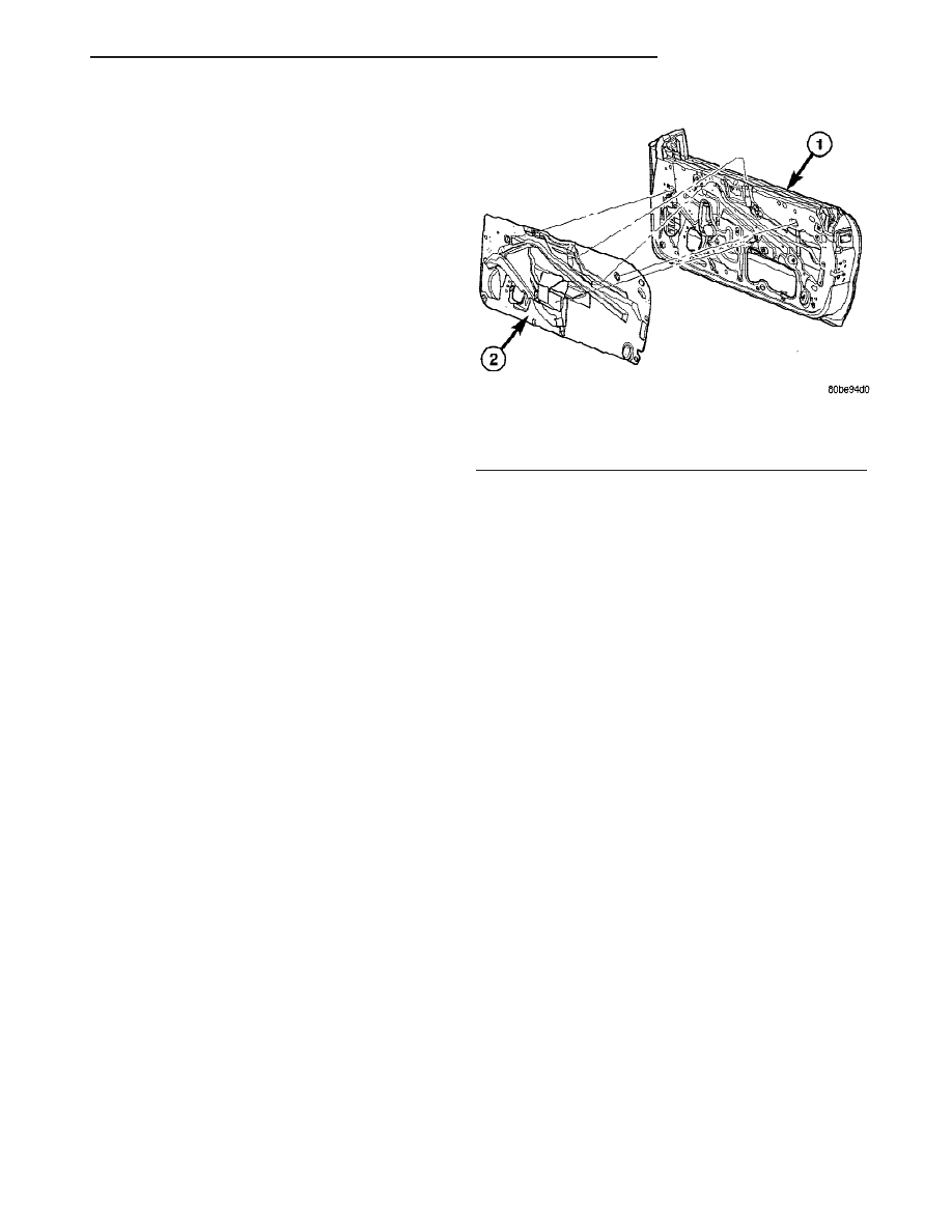
(3) Peel watershield and adhesive away from the

door inner panel. Start in one corner, carefully work-
ing towards the opposite corner. (Fig. 39).

(4) Store watershield flat, adhesive side up, cover-

ing with wax paper or similar if available to prevent
contaminating the adhesive bead.

INSTALLATION

(1) Insure that the adhesive bead is not broken, so

the complete perimeter of the door seal will be main-
tained. Replace any loose/damaged adhesive with
butyl sealer or similar. If repair is not possible,
replace with a new watershield

(2) Place the watershield into position using the

two depressions that locate into the corresponding
holes in the door inner panel. (Fig. 39)

(3) Firmly press the adhesive around the perime-

ter of the door insure complete sealing. Make sure to
properly route wiring and linkages.

(4) Install door speaker, if equipped. (Refer to 8 -

ELECTRICAL/AUDIO/SPEAKER - INSTALLATION)

(5) Install door trim panel. (Refer to 23 - BODY/

DOOR - FRONT/TRIM PANEL - INSTALLATION)

Fig. 39 DOOR WATERSHIELD

1 - DOOR
2 - WATERSHIELD

JR

DOOR - FRONT

23 - 49

DOORS - REAR

TABLE OF CONTENTS

page

page

APPLIQUE

REMOVAL

. . . . . . . . . . . . . . . . . . . . . . . . . . . . . 50

INSTALLATION

. . . . . . . . . . . . . . . . . . . . . . . . . 50

REAR CHECK STRAP

REMOVAL

. . . . . . . . . . . . . . . . . . . . . . . . . . . . . 51

INSTALLATION

. . . . . . . . . . . . . . . . . . . . . . . . . 51

DOOR

REMOVAL

. . . . . . . . . . . . . . . . . . . . . . . . . . . . . 51

INSTALLATION

. . . . . . . . . . . . . . . . . . . . . . . . . 52

ADJUSTMENTS

ADJUSTMENT

. . . . . . . . . . . . . . . . . . . . . . . . 52

DOOR GLASS

REMOVAL

. . . . . . . . . . . . . . . . . . . . . . . . . . . . . 53

INSTALLATION

. . . . . . . . . . . . . . . . . . . . . . . . . 53

EXTERIOR HANDLE

REMOVAL

. . . . . . . . . . . . . . . . . . . . . . . . . . . . . 53

INSTALLATION

. . . . . . . . . . . . . . . . . . . . . . . . . 53

HINGE

REMOVAL

. . . . . . . . . . . . . . . . . . . . . . . . . . . . . 54

INSTALLATION

. . . . . . . . . . . . . . . . . . . . . . . . . 54

LATCH

REMOVAL

. . . . . . . . . . . . . . . . . . . . . . . . . . . . . 55

INSTALLATION

. . . . . . . . . . . . . . . . . . . . . . . . . 55

LATCH STRIKER

REMOVAL

. . . . . . . . . . . . . . . . . . . . . . . . . . . . . 55

INSTALLATION

. . . . . . . . . . . . . . . . . . . . . . . . . 55

TRIM PANEL

REMOVAL

. . . . . . . . . . . . . . . . . . . . . . . . . . . . . 56

INSTALLATION

. . . . . . . . . . . . . . . . . . . . . . . . . 56

WINDOW REGULATOR

REMOVAL

. . . . . . . . . . . . . . . . . . . . . . . . . . . . . 57

INSTALLATION

. . . . . . . . . . . . . . . . . . . . . . . . . 57

WATERSHIELD

REMOVAL

. . . . . . . . . . . . . . . . . . . . . . . . . . . . . 57

INSTALLATION

. . . . . . . . . . . . . . . . . . . . . . . . . 57

APPLIQUE

REMOVAL

(1) Pull the glass run weatherstrip away from the

window opening to access the applique screws. (Refer
to 23 - BODY/WEATHERSTRIP/SEALS/REAR DOOR
GLASS RUN WEATHERSTRIP - REMOVAL)

(2) Remove the screws under the glass run weath-

erstrip (Fig. 1).

(3) Remove the upper push-pin fastener.
(4) Remove the lower inner screw and remove the

applique.

INSTALLATION

(1) Install the applique and the screws.
(2) Install the upper push-in fastener.
(3) Install the lower screw.
(4) Position the glass run weatherstrip back into

position. (Refer to 23 - BODY/WEATHERSTRIP/
SEALS/REAR DOOR GLASS RUN WEATHERSTRIP
- INSTALLATION)

Fig. 1 REAR DOOR APPLIQUE

1 - DOOR
2 - APPLIQUE
3 - SCREWS
4 - INNER SCREW

23 - 50

DOORS - REAR

JR

REAR CHECK STRAP

REMOVAL

(1) Remove rear door trim panel.
(2) Remove the watershield as necessary to gain

access to the latch. (Refer to 23 - BODY/DOORS -
REAR/WATERSHIELD - REMOVAL)

(3) Remove bolt attaching check strap to hinge pil-

lar.

(4) Remove bolt attaching check strap to inner

door panel (Fig. 2).

(5) Remove bolts attaching check strap to door end

frame.

(6) Remove check strap from vehicle.

INSTALLATION

(1) Place check strap into position.
(2) Install bolts attaching check strap to door end

frame.

(3) Install bolt attaching check strap to inner door

panel.

(4) Install bolt attaching check strap to hinge pil-

lar.

(5) Position the watershield back. (Refer to 23 -

BODY/DOORS - REAR/WATERSHIELD - INSTAL-
LATION)

(6) Install rear door trim panel.

DOOR

REMOVAL

(1) Open and support door on a suitable lifting

device.

(2) Mark

hinges

attachment

locations

with

a

grease pencil or other suitable device to aid installa-
tion.

(3) Disengage wire connector at hinge B-pillar

(Fig. 3).

(4) Remove bolts attaching door check strap to

B-pillar.

(5) Remove the nuts and remove the door from

vehicle.

Fig. 2 Rear Door Check Strap

1 - REAR DOOR
2 - CHECK STRAP

Fig. 3 REAR DOOR/HINGES

1 - UPPER HINGE NUTS
2 - UPPER HINGE
3 - ELECTRICAL CONNECTOR
4 - CHECK STRAP
5 - LOWER HINGE
6 - LOWER HINGE NUTS

JR

DOORS - REAR

23 - 51

INSTALLATION

(1) Position door onto the door hinges and install

the nuts (Fig. 4).

(2) Install bolts holding door check strap to hinge

pillar.

(3) Engage wire connector at hinge pillar.
(4) Verify door fit and operation. Adjust the door

for flushness and parallel gaps as necessary. (Refer to
23 - BODY/DOORS - REAR/DOOR - ADJUST-
MENTS).

ADJUSTMENTS

ADJUSTMENT

(1) Align door to achieve equal spacing to sur-

rounding body panels.

(2) Panels should be flush across all gaps. (Refer to

23 - BODY/BODY STRUCTURE/JR - 41 GAP AND
FLUSH - SPECIFICATIONS).

(3) If door needs to be adjusted Fore/Aft loosen

B-pillar to hinge bolts (Fig. 5).

(4) If door needs to be adjusted In/Out loosen door

to hinge nuts.

(5) If door alignment can not be achieved, it maybe

necessary to enlarge (drill) the hinge flange holes to
12.5 mm (1/2 inch).

(6) This may allow extra movement to achieve the

proper alignment.

(7) Remove door and hinge as necessary.

Fig. 4 REAR DOOR/HINGES

1 - UPPER HINGE NUTS
2 - UPPER HINGE
3 - ELECTRICAL CONNECTOR
4 - CHECK STRAP
5 - LOWER HINGE
6 - LOWER HINGE NUTS

Fig. 5 REAR DOOR/HINGES

1 - UPPER HINGE NUTS
2 - UPPER HINGE
3 - ELECTRICAL CONNECTOR
4 - CHECK STRAP
5 - LOWER HINGE
6 - LOWER HINGE NUTS

23 - 52

DOORS - REAR

JR

DOOR (Continued)


Content   ..  661  662  663  664   ..