Chrysler Sebring, Stratus sedan, Sebring Convertible. Manual - part 661


  Index      Chrysler     Chrysler Sebring, Stratus sedan, Sebring Convertible - service repair manual 2001-2007 year


Search            


Content   ..  659  660  661  662   ..


Chrysler Sebring, Stratus sedan, Sebring Convertible. Manual - part 661


(3) Connect wire connector to power door lock

motor.

(4) Connect lock and latch rods from outside door

handle and key cylinder at door latch.

(5) Engage lock and latch rods to clips on inner

door panel.

(6) Connect lock rod from lock button bellcrank.
(7) Position the rear glass run channel back and

install the bolt and nut.

(8) Adjust door latch.
(9) Verify operation of door latch. Readjust if nec-

essary.

(10) Install door trim panel (Refer to 23 - BODY/

DOOR - FRONT/TRIM PANEL - INSTALLATION)

and water dam (Refer to 23 - BODY/DOOR - FRONT/
WATERDAM - INSTALLATION).

ADJUSTMENTS

ADJUSTMENT

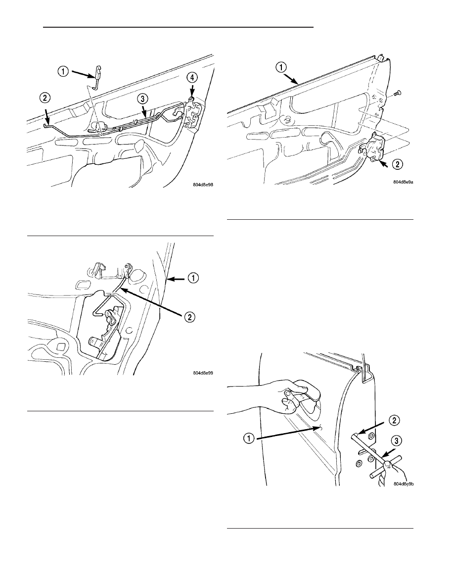
(1) Insert a suitable allen wrench through elon-

gated slot in door end frame and loosen bolt 1/2 to
one full turn (Fig. 24).

(2) Cycle outside door handle twice.
(3) Tighten adjusting screw to 3.4 N·m (30 in. lbs.)

torque.

(4) Verify latch operation.

Fig. 21 Latch and Lock Rod Clips

1 - INSIDE LOCK BUTTON
2 - LATCH ROD
3 - LOCK ROD
4 - DOOR LATCH

Fig. 22 Lock and Latch Rods At Door Latch

1 - DOOR
2 - DOOR LATCH ROD

Fig. 23 Door Latch

1 - DOOR
2 - DOOR LATCH

Fig. 24 Door Latch Adjustment

1 - DOOR
2 - SLOT
3 - ALLEN WRENCH

JR

DOOR - FRONT

23 - 41

LATCH (Continued)

LATCH STRIKER

REMOVAL

(1) Mark outline of door latch striker on B-pillar to

aid in installation.

(2) Remove screws attaching door latch striker to

B-pillar (Fig. 25).

(3) Remove latch striker from vehicle.

NOTE: Be sure to check for any shims between
door latch striker and B-pillar. If any shims are
found, they must be reinstalled with the new door
latch striker to maintain proper door operation.

INSTALLATION

(1) Position door latch striker and any shims on

vehicle.

(2) Loosely install screws attaching latch striker to

B-pillar.

(3) Align latch striker to marks on B-pillar made

previously.

(4) Tighten all fasteners.
(5) Verify door fit and operation. Adjust door latch

striker as necessary.

LOCK BUTTON BELL CRANK

REMOVAL

(1) Remove door trim panel.
(2) Disengage clip holding lock linkage to bell

crank.

(3) Rotate bell crank until retaining ears align

with slots in door panel.

(4) Remove bell crank from door (Fig. 26).

INSTALLATION

(1) Place bell crank into position.
(2) Rotate bell crank until retaining ears align

with slots in door panel.

(3) Engage clip attaching lock linkage to bell

crank.

(4) Install door trim panel.

Fig. 25 Door Latch Striker

1 - B-PILLAR
2 - SHIM
3 - DOOR LATCH STRIKER

Fig. 26 Lock Button Bell Crank – Typical

1 - LOCK BUTTON
2 - LATCH LINKAGE
3 - LOCK LINKAGE
4 - BELL-CRANK

23 - 42

DOOR - FRONT

JR

LOCK CYLINDER

DESCRIPTION

Ignition, door, deck lid, and rear hatch lock cylin-

ders are all codable to the key. Lock barrels, tum-
blers, and tumbler springs are available to allow the
technician to change replacement locks cylinders to
match the customer’s original key set. See the appro-
priate section in this manual for lock cylinder
removal. See the Mopar

t catalogue for part numbers

and lock coding procedures.

REMOVAL

(1) Remove outside door handle.
(2) Remove clip attaching lock cylinder to outside

door panel (Fig. 27).

(3) Disengage clip attaching link to key cylinder.
(4) Remove lock cylinder from outer door panel.

INSTALLATION

(1) Position lock cylinder and gasket in door outer

panel.

(2) Install clip attaching lock cylinder to outside

door panel.

(3) Engage link to key cylinder.
(4) Install outside door handle.

SIDE VIEW MIRROR FLAG/
DOOR GLASS CHANNEL

REMOVAL

(1) Remove side view mirror (Refer to 23 - BODY/

EXTERIOR/SIDE VIEW MIRROR - REMOVAL).

(2) Partially lower the door glass.
(3) Remove inner belt line glass seal.
(4) Remove attaching fasteners (Fig. 28).
(5) Remove the adjustment stud. Count the num-

ber of turns to aid installation.

(6) Remove mirror flag.

INSTALLATION

(1) Align glass into the guide and position the mir-

ror flag on door. (Fig. 28)

(2) Install the adjustment stud and tighten the

number of turns counted in the removal procedure.

(3) Install attaching fasteners and tighten to 7 Nm

(62 in. lbs.).

(4) Install the inner glass seal.
(5) Verify glass fit at mirror flag. Upper edge of

the glass should be flush with the mirror flag top
edge. Adjust the mirror flag position as necessary.
(Fig. 13)

(6) Install side view mirror (Refer to 23 - BODY/EX-

TERIOR/SIDE VIEW MIRROR - INSTALLATION).

Fig. 27 Door Lock Cylinder

1 - DOOR LOCK CYLINDER
2 - DOOR
3 - DOOR LOCK CYLINDER

Fig. 28 SIDE VIEW MIRROR FLAG/DOOR GLASS

CHANNEL

1 - EXTERIOR BOLT
2 - MIRROR FLAG
3 - INTERIOR FASTENERS
4 - U-NUT

JR

DOOR - FRONT

23 - 43

TRIM PANEL

REMOVAL

(1) Roll door glass down.
(2) Disengage two clips attaching speaker grille to

door trim panel. They are at the front of the grille,
one near the top, and the other one at the bottom.

(3) Remove three large washer-headed screws sur-

rounding the speaker (Fig. 29).

(4) Remove access cover at front of door trim

panel. Remove by prying at its rear edge (Fig. 30).

(5) Remove red courtesy reflector from lower tail

or door. Disengage by prying at screwdriver notch at
bottom of reflector.

(6) Remove flag trim panel from door by prying off

at two attachment clips points (Fig. 30).

(7) Remove seven screws attaching door trim panel

to door: (Fig. 29) and (Fig. 30).

(a) One screw is located at lower rear screw

pocket.

(b) Three screws located along the bottom of

door.

(c) One screw located inside handle opening.
(d) One screw located at the upper front.
(e) One screw in the pull cup.

(8) Disengage two hidden clips attaching at the

rear of the trim panel, by prying off at two attach-
ment clip points.

(9) Lift trim panel upward and away from door,

disengage trim panel from upper retainer channel.

(10) Disengage clip attaching latch linkage to back

door handle.

(11) Disconnect electrical connectors as necessary,

including lower foot light, If equipped.

(12) Remove door trim panel from door.

INSTALLATION

(1) Position door trim panel near to door.
(2) Connect

electrical

connectors

as

necessary,

including foot light, if so equipped.

(3) Engage clip attaching latch linkage to inside

door handle.

(4) Lift the door trim slightly to get the lock knob

into its bezel opening on the panel.

(5) Place front portion of upper trim strip flange

into retainer channel, while seating white forward
locator pin into mating hole in sheet metal at front of
door.

(6) Drive screw into forward locator cup.
(7) With rear of panel slightly lifted, engage

remainder of trim strip flange into retainer channel,
working from front to back, pressing down firmly.

(8) Engage two hidden clips attaching rear of door

trim to their mating (green) grommet holes in the
door. Press the rear of the panel firmly in toward the
door, listening for engagement clicking sounds at
BOTH of the clips.

(9) Install seven screws attaching door trim panel

to door: (Fig. 29) and (Fig. 30).

(a) One screw in the pull cup.
(b) One screw located inside handle opening.
(c) One screw located at the upper front.
(d) One screw is located at lower rear screw

pocket.

(e) Three screws located along the bottom of

door.
(10) Snap screw covers closed.
(11) Install three large washer headed screws sur-

rounding the speaker (Fig. 29).

Fig. 29 Lower Door Trim Panel Removal

1 - SCREWS AT SPEAKER LOCATION
2 - BOTTOM OF DOOR TRIM PANEL

Fig. 30 Mirror Bezel and Door Trim Access Cover

1 - FLAG TRIM PANEL
2 - DOOR TRIM ACCESS COVER
3 - INSIDE REMOTE HANDLE
4 - POWER DOOR LOCK SWITCH

23 - 44

DOOR - FRONT

JR


Content   ..  659  660  661  662   ..