Chrysler Sebring, Stratus sedan, Sebring Convertible. Manual - part 641


  Index      Chrysler     Chrysler Sebring, Stratus sedan, Sebring Convertible - service repair manual 2001-2007 year


Search            


Content   ..  639  640  641  642   ..


Chrysler Sebring, Stratus sedan, Sebring Convertible. Manual - part 641


SPEED SENSOR - OUTPUT

DESCRIPTION

The Output Speed Sensor is a two-wire magnetic

pickup device that generates an AC signal as rotation
occurs. It is threaded into the transaxle case (Fig.
315), sealed with an o-ring (Fig. 316), and is consid-
ered a primary input to the Powetrain/Transmission
Control Module.

OPERATION

The Output Speed Sensor provides information on

how fast the output shaft is rotating. As the rear
planetary carrier park pawl lugs pass by the sensor
coil (Fig. 317), an AC voltage is generated and sent to
the PCM/TCM. The PCM/TCM interprets this infor-
mation as output shaft rpm.

The PCM/TCM compares the input and output

speed signals to determine the following:

• Transmission gear ratio

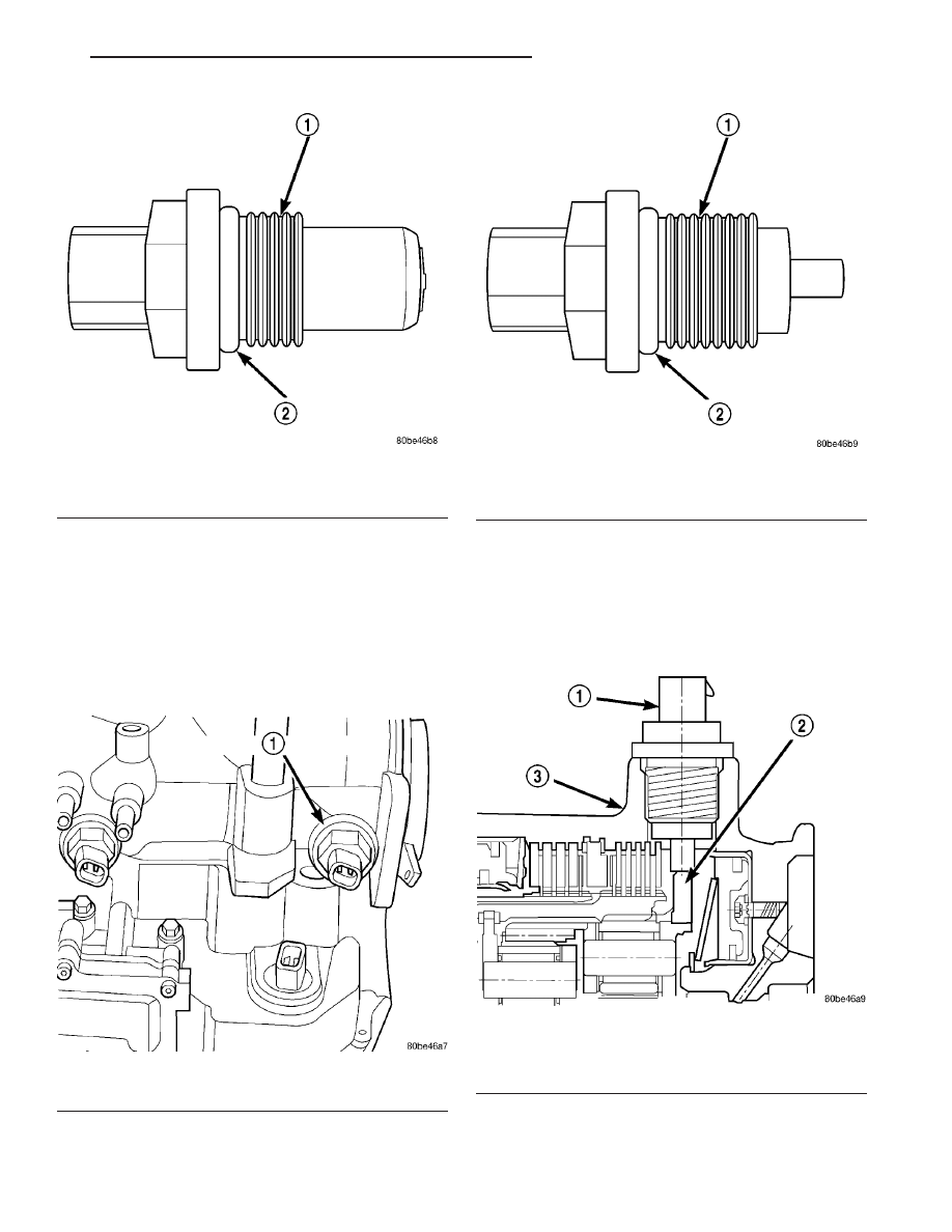
Fig. 314 O-ring Location

1 - INPUT SPEED SENSOR
2 - O-RING

Fig. 315 Output Speed Sensor

1 - OUTPUT SPEED SENSOR

Fig. 316 O-Ring Location

1 - OUTPUT SPEED SENSOR
2 - O-RING

Fig. 317 Sensor Relation to Planet Carrier Park Pawl

1 - OUTPUT SPEED SENSOR
2 - REAR PLANET CARRIER/OUTPUT SHAFT ASSEMBLY
3 - TRANSAXLE CASE

JR

41TE AUTOMATIC TRANSAXLE

21 - 325

SPEED SENSOR - INPUT (Continued)

• Speed ratio error detection

• CVI calculation

VEHICLE SPEED SIGNAL

The vehicle speed signal is taken from the Output

Speed Sensor. The PCM converts this signal into a
pulse per mile signal and sends the vehicle speed
message across the communication bus to the BCM.
The BCM sends this signal to the Instrument Cluster
to display vehicle speed to the driver. The vehicle
speed signal pulse is roughly 8000 pulses per mile.

REMOVAL

(1) Disconnect battery negative cable.
(2) Raise vehicle on hoist.
(3) Disconnect output speed sensor connector (Fig.

318).

(4) Unscrew and remove output speed sensor (Fig.

319).

(5) Inspect speed sensor o-ring (Fig. 320) and

replace if necessary.

INSTALLATION

(1) Verify o-ring is installed into position (Fig.

320).

(2) Install and tighten input speed sensor to 27

N·m (20 ft. lbs.).

(3) Connect speed sensor connector (Fig. 318).
(4) Connect battery negative cable.

Fig. 318 Transmission Connectors

1 - SOLENOID PACK CONNECTOR
2 - INPUT SPEED SENSOR CONNECTOR
3 - OUTPUT SPEED SENSOR CONNECTOR
4 - TRANSMISSION RANGE SENSOR CONNECTOR

Fig. 319 Output Speed Sensor

1 - OUTPUT SPEED SENSOR

Fig. 320 O-ring Location

1 - OUTPUT SPEED SENSOR
2 - O-RING

21 - 326

41TE AUTOMATIC TRANSAXLE

JR

SPEED SENSOR - OUTPUT (Continued)

TORQUE CONVERTER

DESCRIPTION

The torque converter (Fig. 321) is a hydraulic

device that couples the engine crankshaft to the
transmission. The torque converter consists of an
outer shell with an internal turbine, a stator, an
overrunning clutch, an impeller and an electronically
applied converter clutch. The converter clutch pro-
vides reduced engine speed and greater fuel economy
when engaged. Clutch engagement also provides
reduced transmission fluid temperatures. The con-
verter clutch engages in third gear. The torque con-
verter hub drives the transmission oil (fluid) pump.

The torque converter is a sealed, welded unit that

is not repairable and is serviced as an assembly.

Fig. 321 Torque Converter Assembly

1 - TURBINE
2 - IMPELLER
3 - HUB
4 - STATOR
5 - CONVERTER CLUTCH DISC
6 - DRIVE PLATE

JR

41TE AUTOMATIC TRANSAXLE

21 - 327

IMPELLER

The impeller (Fig. 322) is an integral part of the

converter housing. The impeller consists of curved
blades placed radially along the inside of the housing
on the transmission side of the converter. As the con-
verter housing is rotated by the engine, so is the
impeller, because they are one and the same and are
the driving member of the system.

Fig. 322 Impeller

1 - ENGINE FLEXPLATE

4 - ENGINE ROTATION

2 - OIL FLOW FROM IMPELLER SECTION INTO TURBINE
SECTION

5 - ENGINE ROTATION

3 - IMPELLER VANES AND COVER ARE INTEGRAL

21 - 328

41TE AUTOMATIC TRANSAXLE

JR

TORQUE CONVERTER (Continued)


Content   ..  639  640  641  642   ..