Chrysler Sebring, Stratus sedan, Sebring Convertible. Manual - part 640
OPERATION
SOLENOIDS
The solenoids receive electrical power from the
Transmission Control Relay through a single wire.
The PCM/TCM energizes or operates the solenoids
individually by grounding the return wire of the sole-
noid needed. When a solenoid is energized, the sole-
noid valve shifts, and a fluid passage is opened or
closed (vented or applied), depending on its default
operating state. The result is an apply or release of a
frictional element.
The 2/4 and UD solenoids are normally applied,
which by design allow fluid to pass through in their
relaxed or “off” state. This allows transaxle limp-in
(P,R,N,2) in the event of an electrical failure.
The continuity of the solenoids and circuits are
periodically tested. Each solenoid is turned on or off
depending on its current state. An inductive spike
should be detected by the PCM/TCM during this test.
It no spike is detected, the circuit is tested again to
verify the failure. In addition to the periodic testing,
the solenoid circuits are tested if a speed ratio or
pressure switch error occurs.
PRESSURE SWITCHES
The PCM/TCM relies on three pressure switches to
monitor fluid pressure in the L/R, 2/4, and OD
hydraulic circuits. The primary purpose of these
switches is to help the PCM/TCM detect when clutch
circuit hydraulic failures occur. The range for the
pressure switch closing and opening points is 11-23
psi. Typically the switch opening point will be
approximately one psi lower than the closing point.
For example, a switch may close at 18 psi and open
at 17 psi. The switches are continuously monitored
by the PCM/TCM for the correct states (open or
closed) in each gear as shown in the following chart:
PRESSURE SWITCH STATES
GEAR
L/R
2/4
OD
R
OP
OP
OP
P/N
CL
OP
OP
1st
CL
OP
OP
2nd
OP
CL
OP
D
OP
OP
CL
OD
OP
CL
CL
OP = OPEN
CL = CLOSED
A Diagnostic Trouble Code (DTC) will set if the
PCM/TCM senses any switch open or closed at the
wrong time in a given gear.
The PCM/TCM also tests the 2/4 and OD pressure
switches when they are normally off (OD and 2/4 are
tested in 1st gear, OD in 2nd gear, and 2/4 in 3rd
gear). The test simply verifies that they are opera-
tional, by looking for a closed state when the corre-
sponding element is applied. Immediately after a
shift into 1st, 2nd, or 3rd gear with the engine speed
above 1000 rpm, the PCM/TCM momentarily turns
on element pressure to the 2/4 and/or OD clutch cir-
cuits to identify that the appropriate switch has
closed. If it doesn’t close, it is tested again. If the
switch fails to close the second time, the appropriate
Diagnostic Trouble Code (DTC) will set.
REMOVAL
NOTE: If solenoid/pressure switch assembly is
being replaced, the “Quick-Learn” procedure must
be performed. (Refer to 8 - ELECTRICAL/ELEC-
TRONIC
CONTROL
MODULES/TRANSMISSION
CONTROL MODULE - STANDARD PROCEDURE)
(1) Disconnect battery negative cable.
(2) Remove air cleaner assembly.
(3) Disconnect solenoid/pressure switch assembly
connector (Fig. 305).
(4) Disconnect input speed sensor connector (Fig.
305).
(5) Remove input speed sensor (Fig. 306).
(6) Remove
three
(3)
solenoid/pressure
switch
assembly-to-transaxle case bolts (Fig. 307).
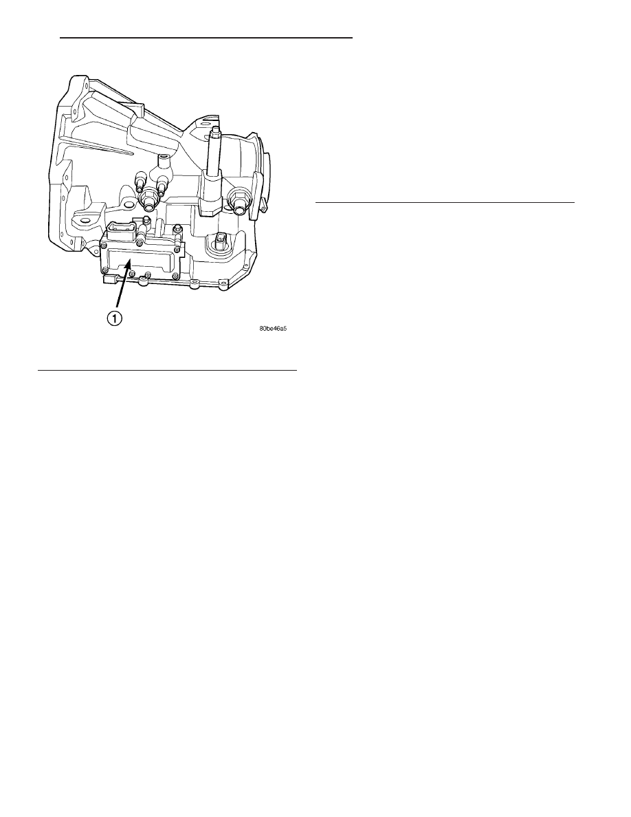
Fig. 304 Solenoid/Pressure Switch Assembly
1 - SOLENOID AND PRESSURE SWITCH ASSEMBLY
JR
41TE AUTOMATIC TRANSAXLE
21 - 321
SOLENOID/PRESSURE SWITCH ASSY (Continued)