Chrysler Sebring, Stratus sedan, Sebring Convertible. Manual - part 636


  Index      Chrysler     Chrysler Sebring, Stratus sedan, Sebring Convertible - service repair manual 2001-2007 year


Search            


Content   ..  634  635  636  637   ..


Chrysler Sebring, Stratus sedan, Sebring Convertible. Manual - part 636


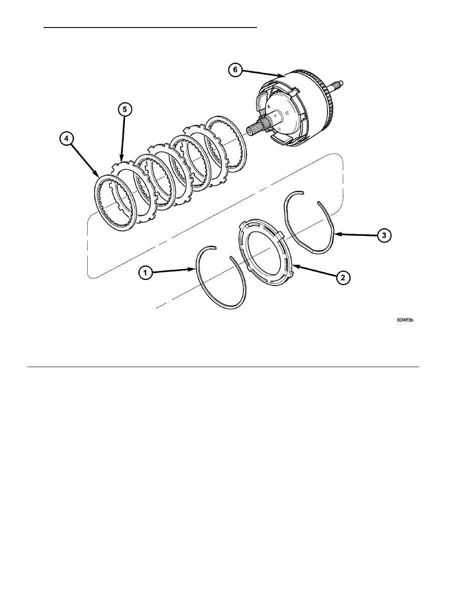
Fig. 259 Overdrive Clutch Assembly

1 - SNAP RING
2 - OD/REVERSE PRESSURE PLATE
3 - SNAP RING (WAVE)

4 - CLUTCH DISC (4)
5 - CLUTCH STEEL (3)
6 - INPUT CLUTCH ASSEMBLY

JR

41TE AUTOMATIC TRANSAXLE

21 - 305

INPUT CLUTCH ASSEMBLY (Continued)

(25) Measure OD clutch pack clearance. Set up

dial indicator on top of the OD/Reverse pressure
plate as shown in (Fig. 260).

(26) Zero dial indicator and apply 30 psi (206 kPa)

air pressure to the overdrive clutch hose on Tool
8391. Measure and record OD clutch pack measure-
ment in four (4) places, 90° apart.

(27) Take average of four measurements and com-

pare with OD clutch pack clearance specification.
The overdrive (OD) clutch pack clearance is
1.07-3.25 mm (0.042-0.128 in.).

If not within specifications, the clutch is not

assembled properly. There is no adjustment for the
OD clutch clearance.

(28) Install reverse clutch pack (two frictions/one

steel) (Fig. 261).

(29) Install reverse clutch reaction plate with the

flat side down towards reverse clutch (Fig. 262).

Fig. 260 Measure OD Clutch Pack Clearance

1 - DIAL INDICATOR
2 - OD/REVERSE REACTION PLATE

Fig. 261 Install Reverse Clutch Pack

1 - REVERSE CLUTCH PLATE
2 - REVERSE CLUTCH DISCS

Fig. 262 Install Reaction Plate

1 - REVERSE CLUTCH REACTION PLATE (FLAT SIDE DOWN)

21 - 306

41TE AUTOMATIC TRANSAXLE

JR

INPUT CLUTCH ASSEMBLY (Continued)

(30) Tap reaction plate down to allow installation

of the reverse clutch snap ring. Install reverse clutch
snap ring (Fig. 263) (Fig. 264).

(31) Pry up reverse reaction plate to seat against

snap ring (Fig. 265).

Fig. 263 Install Reverse Clutch Snap Ring

1 - REVERSE CLUTCH SNAP RING (SELECT)
2 - SCREWDRIVER
3 - REVERSE CLUTCH REACTION PLATE

Fig. 264 Reverse Clutch Assembly

1 - SNAP RING
2 - REACTION PLATE
3 - CLUTCH DISC (2)

4 - CLUTCH PLATE (1)
5 - INPUT CLUTCH ASSEMBLY

Fig. 265 Pry Up Reaction Plate to Seat Against Snap

Ring

1 - SCREWDRIVER
2 - SNAP RING
3 - SCREWDRIVER
4 - MUST RAISE REVERSE REACTION PLATE TO RAISE SNAP
RING

JR

41TE AUTOMATIC TRANSAXLE

21 - 307

INPUT CLUTCH ASSEMBLY (Continued)

(32) Set up a dial indicator on the reverse clutch

pack as shown in (Fig. 266).

(33) Using moderate pressure, press down and

hold (near indicator) reverse clutch disc with screw-
driver or suitable tool and zero dial indicator (Fig.
267). When releasing pressure, indicator should
advance 0.005-0.010. as clutch pack relaxes.

(34) Apply 30 psi (206 kPa) air pressure to the

reverse clutch hose on Tool 8391. Measure and record
reverse clutch pack measurement in four (4) places,
90° apart.

(35) Take average of four measurements and com-

pare with reverse clutch pack clearance specification.
The reverse clutch pack clearance is 0.89-1.37
mm (0.035-0.054 in.). 
Select the proper reverse
clutch snap ring to achieve specifications:

REVERSE CLUTCH SNAP RING THICKNESS

4377195

1.53-1.58 mm (0.060-0.062 in.)

4412871

1.77-1.83 mm (0.070-0.072 in.)

4412872

2.02-2.07 mm (0.080-0.082 in.)

4412873

2.27-2.32 mm (0.090-0.091 in.)

(36) To complete the assembly, reverse clutch and

overdrive clutch must be removed.

(37) Install the #2 needle bearing (Fig. 268).

Fig. 266 Measure Reverse Clutch Pack Clearance

1 - DIAL INDICATOR
2 - REVERSE CLUTCH

Fig. 267 Press Down on Reverse Clutch and Zero

Indicator

1 - DIAL INDICATOR
2 - REVERSE CLUTCH

Fig. 268 Install No. 2 Needle Bearing

1 - #2 NEEDLE BEARING (NOTE 3 SMALL TABS)
2 - TABS UP

21 - 308

41TE AUTOMATIC TRANSAXLE

JR

INPUT CLUTCH ASSEMBLY (Continued)


Content   ..  634  635  636  637   ..