Chrysler Sebring, Stratus sedan, Sebring Convertible. Manual - part 637


  Index      Chrysler     Chrysler Sebring, Stratus sedan, Sebring Convertible - service repair manual 2001-2007 year


Search            


Content   ..  635  636  637  638   ..


Chrysler Sebring, Stratus sedan, Sebring Convertible. Manual - part 637


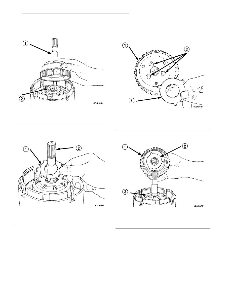
(38) Install the underdrive shaft assembly (Fig.

269).

(39) Install the #3 thrust washer to the underdrive

shaft assembly. Be sure five tabs are seated properly
(Fig. 270).

(40) Install the #3 thrust plate to the bottom of the

overdrive shaft assembly. Retain with petrolatum or
transmission assembly gel (Fig. 271).

(41) Install the overdrive shaft assembly (Fig. 272)

(Fig. 273).

(42) Reinstall overdrive and reverse clutch as

shown. Rechecking these clutch clearances is
not necessary.

Fig. 269 Install Underdrive Shaft Assembly

1 - UNDERDRIVE SHAFT ASSEMBLY
2 - #2 NEEDLE BEARING

Fig. 270 Install No. 3 Thrust Washer

1 - #3 THRUST WASHER (NOTE 5 TABS)
2 - UNDERDRIVE SHAFT ASSEMBLY

Fig. 271 Install No. 3 Thrust Plate

1 - OVERDRIVE SHAFT ASSEMBLY
2 - DABS OF PETROLATUM (FOR RETENTION)
3 - #3 THRUST PLATE (NOTE 3 TABS)

Fig. 272 Install Overdrive Shaft Assembly

1 - OVERDRIVE SHAFT ASSEMBLY
2 - #3 THRUST PLATE
3 - #3 THRUST WASHER

JR

41TE AUTOMATIC TRANSAXLE

21 - 309

INPUT CLUTCH ASSEMBLY (Continued)

Fig. 273 Overdrive/Underdrive Shafts

1 - OVERDRIVE SHAFT
2 - #3 THRUST PLATE (3 TABS)
3 - #3 THRUST WASHER (5 TABS)

4 - UNDERDRIVE SHAFT
5 - #2 NEEDLE BEARING (3 TABS)
6 - INPUT CLUTCH ASSEMBLY

21 - 310

41TE AUTOMATIC TRANSAXLE

JR

INPUT CLUTCH ASSEMBLY (Continued)

OIL PUMP

DESCRIPTION

The oil pump is located in the pump housing inside

the bell housing of the transaxle case (Fig. 274). The
oil pump consists of an inner and outer gear, a hous-
ing, and a cover that also serves as the reaction shaft
support.

OPERATION

As the torque converter rotates, the converter hub

rotates the inner and outer gears. As the gears
rotate,

the

clearance

between

the

gear

teeth

increases in the crescent area, and creates a suction
at the inlet side of the pump. This suction draws
fluid through the pump inlet from the oil pan. As the
clearance between the gear teeth in the crescent area
decreases, it forces pressurized fluid into the pump
outlet and to the valve body.

STANDARD PROCEDURE - OIL PUMP VOLUME
CHECK

Measuring oil pump output volume will determine

if sufficient flow to the transmission oil cooler exists,
and whether or not an internal transmission failure
is present.

Verify that transmission fluid is at the proper

level. If adding fluid is necessary, fill to the proper
level with Mopar

t ATF+4 (Automatic Transmission

Fluid–Type 9602). The following procedure is to
check oil pump output volume:

(1) Using hose cutters or a suitable blade, cut the

“to cooler” (Fig. 275) line off flush with the cooler
inlet fitting and place a collection container under
the open line.

CAUTION: With the fluid set at the proper level,
fluid collection should not exceed (1) quart or inter-
nal damage to the transmission may occur.

(2) Start engine and run at curb idle speed, with

the shift selector in neutral.

(3) If one quart of ATF is collected in 20 seconds or

less, flow is within acceptable limits. If fluid flow is
intermittent or it takes more than 20 seconds to col-
lect one quart of ATF, (Refer to 21 - TRANSMIS-
SION/TRANSAXLE/AUTOMATIC

-

41TE

-

DIAGNOSIS AND TESTING).

(4) Inspect the cooler hose for damage. Replace if

necessary.

(5) Re-connect the to cooler line to the transmis-

sion using a service splice kit. Refer to instructions
inclued with the kit.

(6) Refill

the

transaxle

to

proper

level

with

Mopar

t ATF+4 (Automatic Transmission Fluid–Type

9602).

DISASSEMBLY

When disassembling the transaxle it is necessary

to inspect the oil pump for wear and damage.

(1) Remove the reaction shaft support-to-pump

body bolts (Fig. 276).

(2) Remove reaction shaft support from pump

housing (Fig. 277).

(3) Remove the pump gears (Fig. 278) and check

for wear and damage on pump housing and gears.

Fig. 274 Oil Pump Assembly

1 - PUMP BODY
2 - OUTER GEAR
3 - INNER GEAR
4 - REACTION SHAFT SUPPORT
5 - SEAL RINGS (4)
6 - REACTION SHAFT
7 - CRESCENT

Fig. 275 Transaxle Oil Cooler Fittings

1 - FROM COOLER
2 - TO COOLER

JR

41TE AUTOMATIC TRANSAXLE

21 - 311

(4) Re-install the gears and check clearances.
(5) Measure the clearance between the outer gear

and the pump pocket (Fig. 279). Clearance should be
0.089–0.202 mm (0.0035-0.0079 in.).

Fig. 276 Reaction Support-to-Pump Body Bolts

1 - BOLT (6)
2 - PUMP BODY
3 - REACTION SHAFT SUPPORT

Fig. 277 Reaction Shaft Support

1 - PUMP BODY
2 - PUMP GEARS
3 - REACTION SHAFT SUPPORT

Fig. 278 Oil Pump Assembly

1 - PUMP BODY
2 - OUTER GEAR
3 - INNER GEAR
4 - REACTION SHAFT SUPPORT
5 - SEAL RINGS (4)
6 - REACTION SHAFT
7 - CRESCENT

Fig. 279 Measuring Outer Gear-to-Pocket

1 - FEELER GAUGE
2 - OUTER GEAR
3 - PUMP BODY

21 - 312

41TE AUTOMATIC TRANSAXLE

JR

OIL PUMP (Continued)


Content   ..  635  636  637  638   ..