Chrysler Sebring, Stratus sedan, Sebring Convertible. Manual - part 630


  Index      Chrysler     Chrysler Sebring, Stratus sedan, Sebring Convertible - service repair manual 2001-2007 year


Search            


Content   ..  628  629  630  631   ..


Chrysler Sebring, Stratus sedan, Sebring Convertible. Manual - part 630


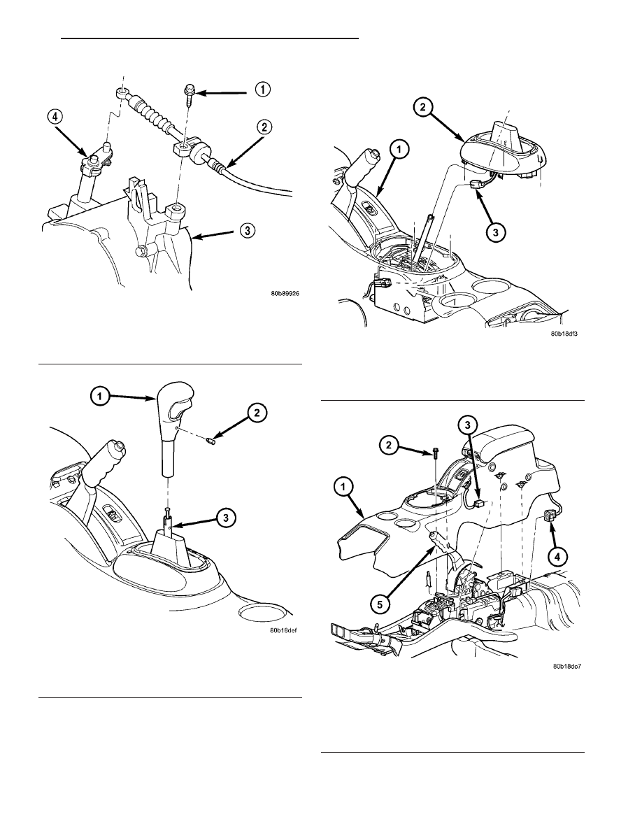
Fig. 199 Gearshift Cable at Transaxle

1 - SCREW
2 - CABLE
3 - TRANSAXLE
4 - SHIFT LEVER

Fig. 200 Gearshift Knob

1 - GEARSHIFT KNOB
2 - SET SCREW
3 - GEARSHIFT MECHANISM

Fig. 201 Gearshift Bezel

1 - CENTER CONSOLE ASSEMBLY
2 - GEARSHIFT BEZEL
3 - LAMP CONNECTOR

Fig. 202 Center Console Assembly

1 - CENTER CONSOLE
2 - SCREW
3 - IF EQUIPPED
4 - IF EQUIPPED
5 - PARK BRAKE HANDLE

JR

41TE AUTOMATIC TRANSAXLE

21 - 281

GEARSHIFT CABLE (Continued)

(9) Loosen nut on shift cable adjust lever (Fig.

203).

(10) Using a flat blade pry tool, remove the shifter

cable core end from the shift lever pin (Fig. 204).

(11) Using a flat blade pry tool, pry the cable con-

duit clip up from the shifter bracket. Pull up on the
cable conduit and remove from bracket (Fig. 204).

(12) Raise vehicle on hoist.
(13) Remove the cable grommet from the floor pan

area (Fig. 205).

(14) Carefully remove the cable from the under-

body by unfolding the cable retainer clip (Fig. 205) as
you go along.

INSTALLATION

(1) Install cable assy. into floor pan tunnel hole

and secure grommet. If necessary, use a synthetic
based lubricant to aid in grommet installation.

(2) Position cable into retainer clip (Fig. 205) and

tighten clip to secure cable. Route cable up towards
transaxle shift lever.

(3) Lower vehicle.
(4) Install cable to transaxle and tighten screw to

14 N·m (125 in. lbs.) (Fig. 199).

(5) Install cable to transaxle shift lever (Fig. 199).
(6) Connect cable to shifter conduit bracket and

shift pin. Install cable retaining clip (Fig. 204).

(7) Verify transaxle shift lever and floor shifter

lever are in the PARK position.

(8) Tighten cable adjuster nut (Fig. 203) to 23 N·m

(200 in. lbs.).

(9) Install center console assembly (Fig. 202).
(10) Install gearshift bezel (Fig. 201).
(11) Install gearshift knob (Fig. 200) and tighten

set screw to 2 N·m (20 in.lbs.).

(12) Verify proper cable adjustment. Engine starter

should only engage in PARK and NEUTRAL gear
shifter positions. If adjustment is required, (Refer to
21 - TRANSMISSION/TRANSAXLE/AUTOMATIC -
41TE/GEAR SHIFT CABLE - ADJUSTMENTS)

Fig. 203 Shift Cable Adjust Lever Nut—Typical

1 - ACCESS HOLE

Fig. 204 Gearshift Cable at Floor Shifter

1 - CLIP
2 - CABLE
3 - CONDUIT BRACKET
4 - SHIFT PIN

Fig. 205 Gearshift Cable Routing

1 - CABLE
2 - RETAINER CLIP
3 - GROMMET

21 - 282

41TE AUTOMATIC TRANSAXLE

JR

GEARSHIFT CABLE (Continued)

ADJUSTMENTS

GEARSHIFT LINKAGE ADJUSTMENT

Normal operation of the Park/Neutral Position

Switch provides a quick check to confirm proper link-
age adjustment.

Move the selector level slowly forward until it

clicks into the (P) Park position. The starter should
operate.

After checking the (P) position, move selector

slowly toward the (N) Neutral position until lever is
in the (N) position. If the starter will also operate at
this point the gearshift linkage is properly adjusted.
If the starter fails to operate in either position, link-
age adjustment is required.

ADJUSTMENT

(1) Set parking brake.
(2) Remove the gearshift knob set screw and knob.
(3) Remove gearshift selector bezel and lamp wir-

ing.

(4) Install the gearshift knob set screw and knob.
(5) Place gearshift lever in the (P) (PARK) posi-

tion.

(6) Loosen the gearshift cable adjuster nut at the

shifter assembly (Fig. 206).

(7) Move the gearshift lever on the transaxle to

the park position.

(8) Verify the shift lever and transaxle are in park

position. Tighten the gearshift cable adjuster nut at
the shifter assembly. The gearshift linkage should
now be properly adjusted.

(9)

Check adjustment as follows:

• Detent position for neutral and drive should be

within limits of hand lever gate stops.

• Key start must occur only when shift lever is in

park or neutral positions.

GEARSHIFT MECHANISM

REMOVAL

(1) Disconnect negative battery cable and isolate.
(2) Remove the gearshift knob set screw and knob

(Fig. 207).

(3) Remove gearshift bezel (Fig. 208). Disconnect

range indicator lamp connector.

(4) Remove center console assembly (Fig. 209).
(5) Loosen nut on shift cable adjust lever.
(6) Using a flat blade pry tool, remove the shifter

cable core end from the shift lever pin (Fig. 210).

Fig. 206 Shift Cable Adjust Lever Nut

1 - CONSOLE
2 - ACCESS HOLE
3 - SHIFTER HANDLE

Fig. 207 Gearshift Knob

1 - GEARSHIFT KNOB
2 - SET SCREW
3 - GEARSHIFT MECHANISM

JR

41TE AUTOMATIC TRANSAXLE

21 - 283

GEARSHIFT CABLE (Continued)

(7) Using a flat blade pry tool, pry the cable con-

duit clip up from the shifter bracket. Pull up on the
cable conduit and remove from bracket (Fig. 210).

(8) Release interlock cable adjuster end by insert-

ing pointed object into shift bracket to disengage lock
(Fig. 211). Unsnap the shifter/ignition interlock cable
adjuster end from the slot in the gearshift mecha-
nism bracket and disconnect cable core from shifter
assembly (Fig. 212).

(9) Disconnect Autostick connector (if equipped)

(Fig. 213).

(10) Remove the five nuts at the base of the shifter

assembly. Remove assembly from vehicle (Fig. 214).

Fig. 208 Gearshift Bezel

1 - CENTER CONSOLE ASSEMBLY
2 - GEARSHIFT BEZEL
3 - LAMP CONNECTOR

Fig. 209 Center Console Assembly

1 - CENTER CONSOLE
2 - SCREW
3 - IF EQUIPPED
4 - IF EQUIPPED
5 - PARK BRAKE HANDLE

Fig. 210 Gearshift Cable at Floor Shifter—Typical

1 - CLIP
2 - CABLE
3 - CONDUIT BRACKET
4 - SHIFT PIN

21 - 284

41TE AUTOMATIC TRANSAXLE

JR

GEARSHIFT MECHANISM (Continued)


Content   ..  628  629  630  631   ..