Chrysler Sebring, Stratus sedan, Sebring Convertible. Manual - part 559


  Index      Chrysler     Chrysler Sebring, Stratus sedan, Sebring Convertible - service repair manual 2001-2007 year


Search            


Content   ..  557  558  559  560   ..


Chrysler Sebring, Stratus sedan, Sebring Convertible. Manual - part 559


(4) If not previously lifted, raise vehicle. (Refer to

LUBRICATION

&

MAINTENANCE/HOISTING

-

STANDARD PROCEDURE)

(5) Remove left front wheel and tire assembly.
(6) Remove wheel opening forward splash shield.
(7) Remove power steering fluid pressure hose,

then return hose from power steering gear (Fig. 12).

(8) Remove air shield below left end of bumper

reinforcement.

(9) Remove clamp and return hose (to reservoir)

from right end of return hose tube below the bumper
reinforcement (Fig. 12).

(10) Remove tube mounting clips from bumper

reinforcement (Fig. 12).

(11) Remove return hose tube from routing clips

along left frame rail.

(12) Move steering gear end of return hose tube to

outside of frame rail.

(13) Pull return hose with tube forward, snaking it

between ABS ICU and frame rail. Remove return
hose from vehicle.

RETURN HOSE TO RESERVOIR

(1) Remove remote ground cable from ground stud

on left shock tower. Isolate ground cable from vehicle
by placing isolator on stud as shown (Fig. 10).

(2) Siphon power steering fluid from power steer-

ing fluid reservoir.

(3) Remove screw fastening power steering fluid

reservoir to engine coolant recovery bottle (Fig. 12).

(4) Lift reservoir off guide on engine coolant recov-

ery bottle.

(5) Remove hose clamp attaching power steering

fluid return hose to reservoir (Fig. 12).

(6) Remove power steering fluid return hose from

reservoir.

(7) Remove vehicle’s front fascia. (Refer to 13 -

FRAMES & BUMPERS/BUMPERS/FRONT FASCIA
- REMOVAL)

(8) If not previously lifted, raise vehicle. (Refer to

LUBRICATION

&

MAINTENANCE/HOISTING

-

STANDARD PROCEDURE)

(9) Remove clamp and return hose (to reservoir)

from right end of return hose tube below the bumper
reinforcement (Fig. 12).

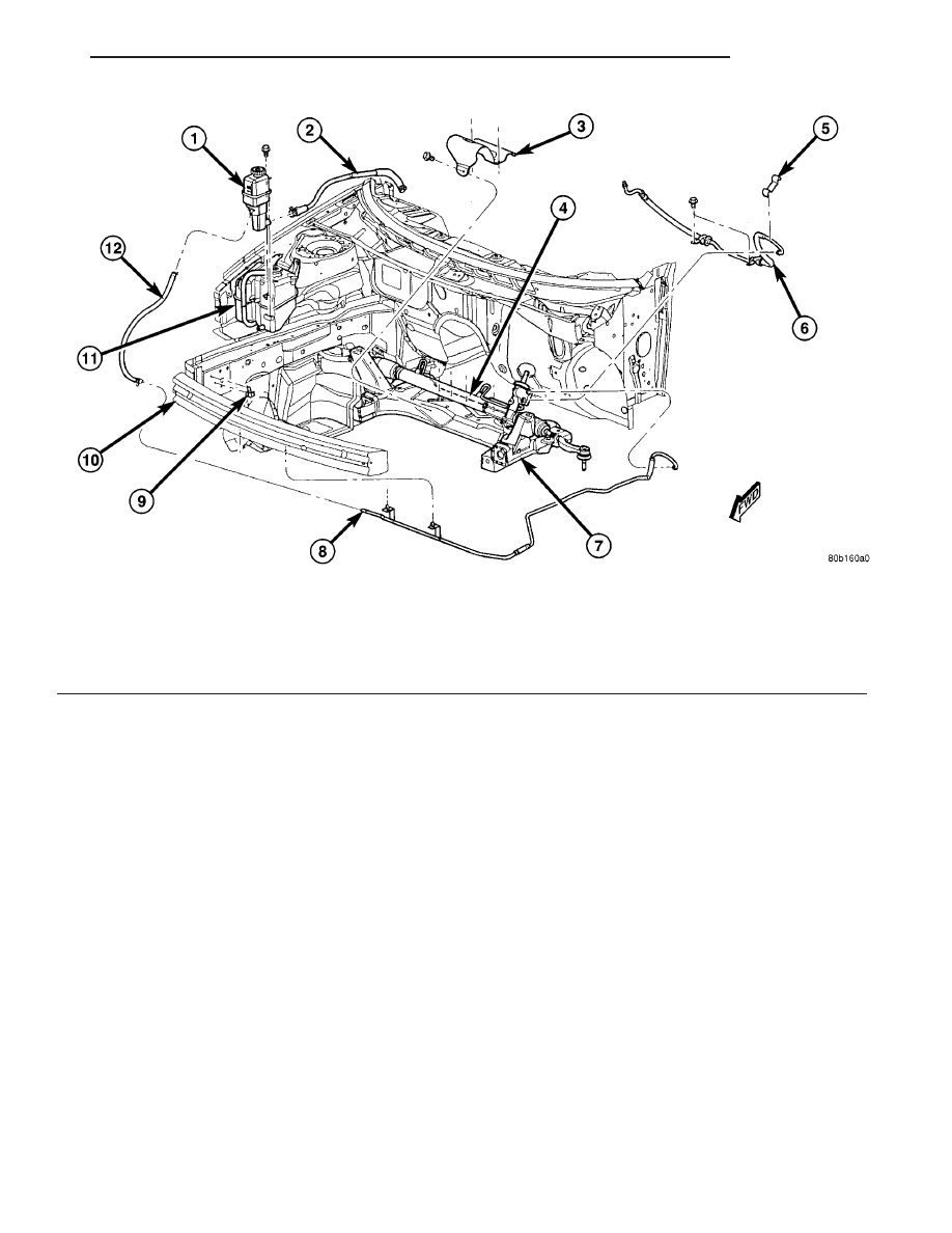
Fig. 12 Power Steering Hoses & Reservoir

1 - FLUID RESERVOIR
2 - SUPPLY HOSE
3 - STEERING GEAR HEAT SHIELD
4 - POWER STEERING GEAR
5 - CLIP
6 - PRESSURE HOSE

7 - FRONT SUSPENSION CROSSMEMBER
8 - RETURN HOSE WITH TUBE
9 - CLIP
10 - FRONT BUMPER REINFORCEMENT
11- COOLANT RECOVERY BOTTLE
12 - RETURN HOSE

JR

PUMP

19 - 35

HOSE - RETURN (Continued)

(10) Remove the return hose from routing clip on

inside of right frame rail (Fig. 12).

(11) Remove power steering fluid return hose.

INSTALLATION

WARNING:

POWER

STEERING

FLUID,

ENGINE

PARTS

AND

EXHAUST

SYSTEM

MAY

BE

EXTREMELY HOT IF ENGINE HAS BEEN RUNNING.
DO NOT START ENGINE WITH ANY LOOSE OR DIS-
CONNECTED HOSES. DO NOT ALLOW HOSES TO
TOUCH HOT EXHAUST MANIFOLD OR CATALYST.

NOTE: Cap all open ends of hoses, power steering
pump fittings and steering gear ports to prevent the
entry of foreign material into the components.

The return hose can be serviced as two separate

pieces. They are the Return Hose With Tube and the
Return Hose To Reservoir.

RETURN HOSE WITH TUBE

(1) Install hose with tube in vehicle using the

reverse of removal. Guide return hose with tube rear-
ward, snaking it between ABS ICU and frame rail.

(2) Install return hose tube into routing clips along

left frame rail.

(3) Install tube along bottom of bumper reinforce-

ment using routing clips (Fig. 12).

(4) Install return hose (to reservoir) on right end of

return hose tube below the bumper reinforcement
(Fig. 12). Install clamp securing hose in place.

(5) Install air shield below left end of bumper rein-

forcement.

(6) Using a lint free towel, wipe clean open power

steering hose ends and power steering gear port.

(7) Install NEW O-rings on power steering hose

ends to steering gear.

(8) Lubricate O-rings using fresh clean power

steering fluid.

(9) Install power steering fluid return hose to

power steering gear. Tighten tube nut to 31 N·m (275
In. lbs.).

(10) Install power steering fluid pressure hose to

power steering gear. Tighten tube nut to 31 N·m (275
In. lbs.).

(11) Install wheel opening forward splash shield.
(12) Install front fascia. (Refer to 13 - FRAMES &

BUMPERS/BUMPERS/FRONT

FASCIA

-

REMOVAL)

(13) Install left front wheel and tire assembly. Pro-

gressively tighten all wheel lug nuts using a criss-
cross pattern to 135 N·m (100 ft. lbs.) torque.

(14) Lower vehicle.
(15) Install remote battery ground cable on ground

stud located on left shock tower.

(16) Fill reservoir with fluid and bleed system

using Power Steering Pump Initial Operation stan-
dard procedure. (Refer to 19 - STEERING/PUMP -
STANDARD PROCEDURE)

(17) Check for leaks.

RETURN HOSE TO RESERVOIR

(1) Install return hose into routing clip on inside of

right frame rail (Fig. 12).

(2) Install return hose (to reservoir) on right end of

return hose tube below the bumper reinforcement
(Fig. 12). Install clamp securing hose in place.

(3) Install front fascia. (Refer to 13 - FRAMES &

BUMPERS/BUMPERS/FRONT

FASCIA

-

REMOVAL)

(4) Lower vehicle.
(5) Install power steering fluid return hose on

power steering fluid reservoir fitting. Be sure hose
clamp is installed on hose past upset bead on
power steering reservoir fitting.

(6) Slide reservoir down over guide on engine cool-

ant recovery bottle.

(7) Install power steering fluid reservoir mounting

screw (Fig. 12).

(8) Fill reservoir with fluid and bleed system using

Power Steering Pump Initial Operation standard pro-
cedure. (Refer to 19 - STEERING/PUMP - STAN-
DARD PROCEDURE)

(9) Check for leaks.

HOSE - SUPPLY

REMOVAL

WARNING:

POWER

STEERING

FLUID,

ENGINE

PARTS

AND

EXHAUST

SYSTEM

MAY

BE

EXTREMELY HOT IF ENGINE HAS BEEN RUNNING.
DO NOT START ENGINE WITH ANY LOOSE OR DIS-
CONNECTED HOSES. DO NOT ALLOW HOSES TO
TOUCH HOT EXHAUST MANIFOLD OR CATALYST.

NOTE: Cap all open ends of hoses, fittings and
ports to prevent the entry of foreign material into
the components.

(1) Remove remote ground cable from ground stud

on left shock tower. Isolate ground cable from vehicle
by placing isolator on stud as shown (Fig. 10).

(2) Siphon as much power steering fluid as possi-

ble out of power steering fluid reservoir.

(3) Remove screw fastening reservoir to engine

coolant recovery bottle (Fig. 12).

(4) Lift reservoir off guide on engine coolant recov-

ery bottle.

19 - 36

PUMP

JR

HOSE - RETURN (Continued)

(5) Remove hose clamp attaching supply hose to

reservoir, then remove supply hose from reservoir
(Fig. 12).

(6) Remove hose clamp attaching supply hose to

power steering pump supply fitting, then remove
supply hose from supply fitting (Fig. 13) (Fig. 14).

(7) Remove supply hose from vehicle.

INSTALLATION

(1) Install supply hose down past engine and onto

power steering pump supply fitting (Fig. 13) (Fig.
14). Install clamp.Be sure hose clamp is installed
on hose past upset bead on fitting.

(2) Install power steering fluid supply hose onto

power steering fluid reservoir fitting (Fig. 12). Install
clamp. Be sure hose clamp is installed on hose
past upset bead on power steering reservoir fit-
ting.

(3) Slide reservoir down over guide on engine cool-

ant recovery bottle.

(4) Install power steering fluid reservoir mounting

screw and tighten to 6 N·m (53 in. lbs.).

(5) Install remote battery ground cable on ground

stud located on left shock tower.

(6) Fill power steering pump fluid reservoir to the

proper level.

(7) Start the engine and let run for a few seconds,

then turn the engine off.

(8) Fill power steering pump fluid reservoir to the

proper level and perform Power Steering Pump Ini-
tial Operation standard procedure. (Refer to 19 -
STEERING/PUMP - STANDARD PROCEDURE)

(9) Check for leaks.

RESERVOIR

DESCRIPTION

All vehicles use a remote mounted power steering

fluid reservoir. The reservoir is mounted to the
engine coolant recovery bottle on the right side of the
engine compartment (Fig. 12). Coolant level is read
through the side of the bottle.

REMOVAL

(1) Remove remote ground cable from ground stud

on left shock tower. Isolate ground cable from vehicle
by placing isolator on stud as shown (Fig. 10).

Fig. 13 Pump Mounting To Engine (2.0L/2.4L)

1 - DRIVE BELT
2 - PULLEY
3 - PRESSURE HOSE
4 - POWER STEERING PUMP
5 - SUPPLY HOSE

Fig. 14 Pump Mounting To Engine (2.7L)

1 - SUPPLY HOSE
2 - DRIVE BELT
3 - PULLEY
4 - PRESSURE HOSE
5 - POWER STEERING PUMP

JR

PUMP

19 - 37

HOSE - SUPPLY (Continued)

(2) Using a siphon pump, remove as much power

steering fluid as possible from the power steering
fluid reservoir.

(3) Remove screw fastening reservoir to engine

coolant recovery bottle (Fig. 12).

(4) Lift reservoir off guide on engine coolant recov-

ery bottle.

(5) Remove hose clamps attaching power steering

fluid supply hose and return hose to reservoir.

(6) Remove power steering fluid supply and return

hoses from reservoir and remove reservoir from vehi-
cle.

INSTALLATION

(1) Install power steering fluid return and supply

hoses on power steering fluid reservoir fittings (Fig.
12). Be sure both hose clamps are installed on
hose past upset bead on power steering reser-
voir fittings.

(2) Slide reservoir down over guide on engine cool-

ant recovery bottle.

(3) Install power steering fluid reservoir mounting

screw and tighten to 6 N·m (53 in. lbs.).

(4) Install remote battery ground cable on ground

stud located on left shock tower.

(5) Fill power steering pump fluid reservoir to the

proper level.

(6) Start the engine and let run for a few seconds,

then turn the engine off.

(7) Adjust fluid level if necessary. Repeat steps (5)

and (6) until the fluid level remains constant after
running the engine. If necessary perform Power
Steering Pump Initial Operation standard procedure.
(Refer to 19 - STEERING/PUMP - STANDARD PRO-
CEDURE)

(8) Check for leaks.

19 - 38

PUMP

JR

RESERVOIR (Continued)


Content   ..  557  558  559  560   ..