Chrysler Sebring, Stratus sedan, Sebring Convertible. Manual - part 538


  Index      Chrysler     Chrysler Sebring, Stratus sedan, Sebring Convertible - service repair manual 2001-2007 year


Search            


Content   ..  536  537  538  539   ..


Chrysler Sebring, Stratus sedan, Sebring Convertible. Manual - part 538


REAR BUMPER
REINFORCEMENT

REMOVAL

(1) Remove rear fascia.
(2) Support bumper reinforcement on a suitable

lifting device.

(3) Mark position of nuts on frame rail to aid in

installation.

(4) Remove nuts attaching rear bumper reinforce-

ment to frame rail (Fig. 4).

(5) Remove bumper reinforcement from vehicle.

INSTALLATION

(1) Position rear bumper reinforcement on vehicle.
(2) Install nuts attaching bumper reinforcement to

frame rail. Use marks made previously to properly
position bumper reinforcement.

(3) Tighten nuts to 28 N·m (250 in. lbs.) torque.
(4) Install rear fascia.

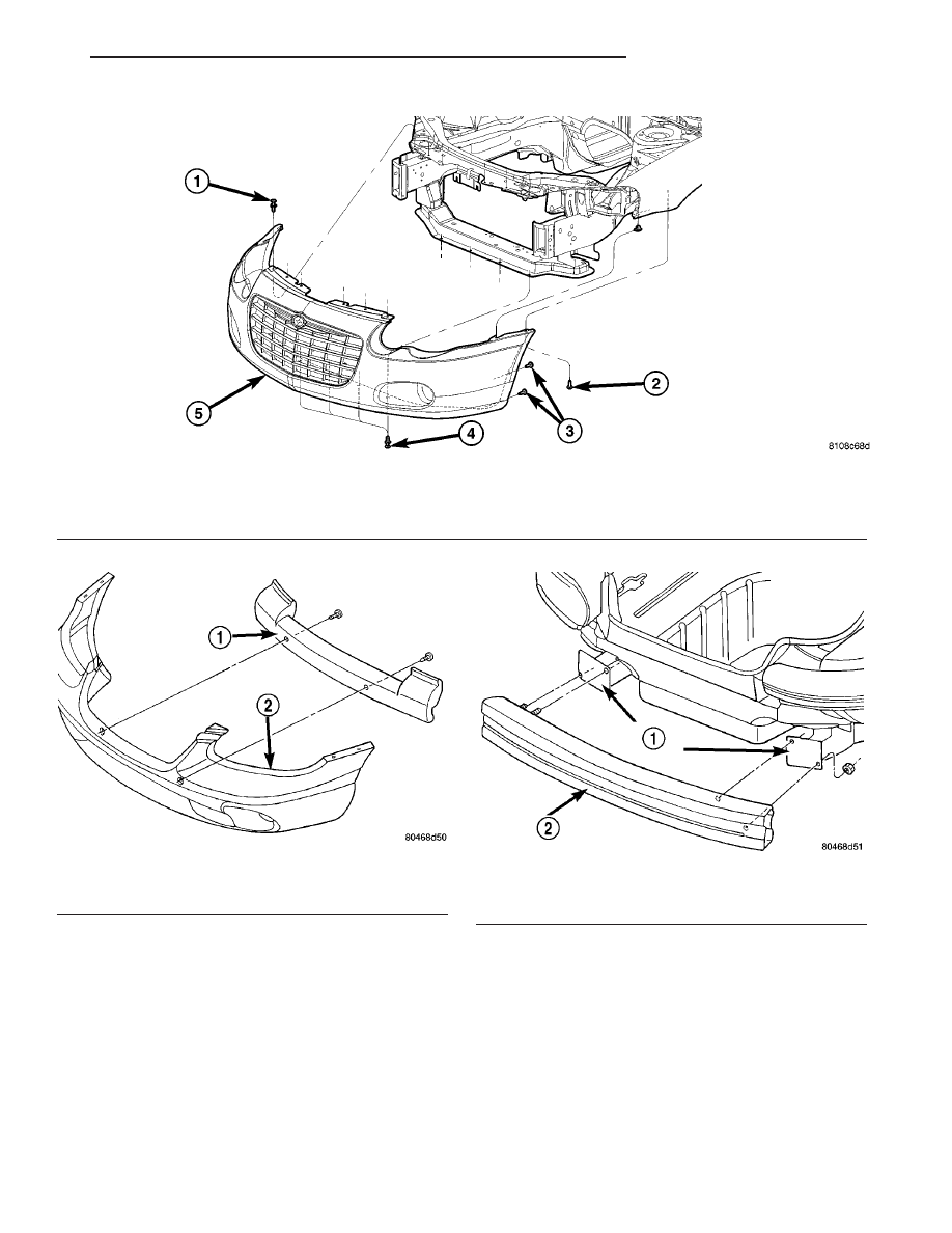
Fig. 2 FRONT FASCIA - JR-27

1 - PUSH PIN(S) TO UPPER RADIATOR CROSSMEMBER
2 - SCREW/WASHER FRONT FASCIA TO FRONT FENDER
3 - SCREW/WASHER FRONT FASCIA TO SPLASH SHIELD

4 - PUSH PIN(S) FRONT FASCIA TO LOWER CROSSMEMBER
5 - FRONT FASCIA

Fig. 3 Front Bumper Energy Management Foam

1 - FRONT BUMPER ENERGY MANAGEMENT FOAM
2 - FRONT FASCIA

Fig. 4 Rear Bumper Reinforcement

1 - FRAME RAIL
2 - FRONT BUMPER REINFORCEMENT

JR

FRAME & BUMPERS

13 - 3

FRONT FASCIA (Continued)

REAR FASCIA

REMOVAL

REMOVAL - JR-41

(1) Release decklid latch and open decklid.
(2) Remove left rear tail lamp and disengage

license plate wire connector from tail lamp. (Refer to
8 - ELECTRICAL/LAMPS/LIGHTING - EXTERIOR/
TAIL LAMP - REMOVAL).

(3) Peel back trunk carpeting at tail lamps and

remove nut and washer from fascia to quarter panel
bracket. Discard nut and washer.

(4) Remove push-in fasteners attaching decklid

slam bumpers to top of fascia.

(5) Remove push-in fastener attaching center of

fascia to rear closure panel.

(6) Remove screws attaching fascia to rear wheel-

house splash shields (Fig. 5).

(7) Remove screws attaching fascia to quarter

panel at the wheelhouse opening.

(8) Slide fascia rearward to disengage hooks hold-

ing fascia to bottom of quarter panel.

(9) Remove fascia from vehicle.

REMOVAL - JR-27

(1) Release decklid latch and open decklid.
(2) Remove tail lamps.
(3) Remove push-in fasteners attaching decklid

slam bumpers to top of fascia.

(4) Remove push-in fastener attaching center of

fascia to rear closure panel.

(5) Remove screws attaching fascia to rear wheel-

house splash shields (Fig. 6).

(6) Remove screws attaching fascia to quarter

panel at the wheelhouse opening.

(7) Slide fascia rearward to disengage hooks hold-

ing fascia to bottom of quarter panel.

(8) Remove fascia from vehicle.

INSTALLATION

INSTALLATION - JR-41

(1) Ensure that the energy management foam is

properly installed in rear fascia.

(2) Position fascia on vehicle.
(3) Slide fascia forward to engage hooks attaching

fascia to bottom of quarter panel.

(4) Install push-in fastener attaching center of fas-

cia to rear closure panel.

(5) Install

push-in

fasteners

attaching

decklid

slam bumpers to top of fascia.

(6) Install new nut and washer to fascia to quarter

panel bracket located in the trunk area.

(7) Install screws attaching fascia to quarter panel

at wheelhouse opening.

(8) Install fasteners attaching fascia to rear wheel-

house splash shields.

(9) Engage license plate wire connector to left tail

lamp.

(10) Install tail lamps. (Refer to 8 - ELECTRICAL/

LAMPS/LIGHTING

-

EXTERIOR/TAIL

LAMP

-

INSTALLATION).

Fig. 5 REAR FASCIA

1 - NUT (FASCIA TO QUARTER PANEL)
2 - SCREW AND WASHER (FASCIA TO QUARTER PANEL)
3 - SCREW (FASCIA TO SPLASHSHIELD)
4 - REAR FASCIA
5 - PUSH PIN (FASCIA TO DECKLID OPENING REINFORCMENT)
6 - LICENSE PLATE LAMP HARNESS
7 - BUMPER REINFORCEMENT

Fig. 6 REAR FASCIA

1 - REAR BUMPER REINFORCEMENT
2 - TRUNK
3 - QUARTER PANEL
4 - REAR FASCIA

13 - 4

FRAME & BUMPERS

JR

INSTALLATION - JR-27

(1) Ensure that the energy management foam is

properly installed in rear fascia (Fig. 7).

(2) Slide fascia forward to engage hooks attaching

fascia to bottom of quarter panel.

(3) Install push-in fastener attaching center of fas-

cia to rear closure panel.

(4) Install

push-in

fasteners

attaching

decklid

slam bumpers to top of fascia.

(5) Install screws attaching fascia to quarter panel

at wheelhouse opening.

(6) Install fasteners attaching fascia to rear wheel-

house splash shields.

(7) Engage license plate wire connector to left tail

lamp.

(8) Install tail lamps. (Refer to 8 - ELECTRICAL/

LAMPS/LIGHTING

-

EXTERIOR/TAIL

LAMP

-

INSTALLATION).

FRAME

SPECIFICATIONS - FRAME DIMENSIONS

Frame dimensions are listed in metric scale. All

dimensions are from center to center of Principal
Locating Point (PLP), or from center to center of PLP
and fastener location.

VEHICLE PREPARATION

Position the vehicle on a level work surface. Using

screw or bottle jacks, adjust the vehicle PLP heights
to the specified dimension above a level work surface.
Vertical dimensions can be taken from the work sur-
face to the locations indicated were applicable.

Fig. 7 REAR BUMPER ENERGY MANAGEMENT

FOAM

1 - ENERGY MANAGEMENT FOAM
2 - REAR BUMPER FASCIA

JR

FRAME & BUMPERS

13 - 5

REAR FASCIA (Continued)

INDEX

DESCRIPTION

FIGURE

ENGINE COMPARTMENT TOP VIEW

8

ENGINE COMPARTMENT SIDE VIEW

9

FORWARD FRAME SECTION BOTTOM VIEW

10

REAR FRAME SECTION SIDE VIEW

11

REAR FRAME SECTION BOTTOM VIEW

12

Fig. 8 ENGINE COMPARTMENT TOP VIEW

13 - 6

FRAME & BUMPERS

JR

FRAME (Continued)


Content   ..  536  537  538  539   ..