Chrysler Sebring, Stratus sedan, Sebring Convertible. Manual - part 506


  Index      Chrysler     Chrysler Sebring, Stratus sedan, Sebring Convertible - service repair manual 2001-2007 year


Search            


Content   ..  504  505  506  507   ..


Chrysler Sebring, Stratus sedan, Sebring Convertible. Manual - part 506


OPERATION

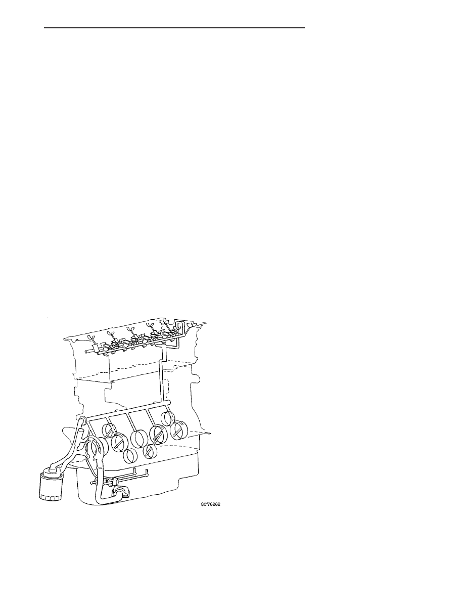
Engine oil drawn up through the pickup tube and

is pressurized by the oil pump and routed through
the full-flow filter to the main oil gallery running the
length of the cylinder block. A diagonal hole in each
bulkhead feeds oil to each main bearing. Drilled pas-
sages within the crankshaft route oil from main bear-
ing journals to connecting rod journals. Balance shaft
lubrication is provided through an oil passage from
the number one main bearing cap through the bal-
ance shaft carrier support leg. This passage directly
supplies oil to the front bearings and internal
machined passages in the shafts that routes oil from
front to the rear shaft bearing journals. A vertical
hole at the number five bulkhead routes pressurized
oil through a restrictor (integral to the cylinder head
gasket) up past a cylinder head bolt to an oil gallery
running the length of the cylinder head. The cam-
shaft journals are partially slotted to allow a prede-
termined amount of pressurized oil to pass into the
bearing cap cavities. Lubrication of the camshaft
lobes are provided by small holes in the camshaft
bearing caps that are directed towards each lobe. Oil
returning to the pan from pressurized components
supplies lubrication to the valve stems. Cylinder
bores and wrist pins are splash lubricated from
directed slots on the connecting rod thrust collars
(Fig. 82).

DIAGNOSIS AND TESTING

CHECKING ENGINE OIL PRESSURE

(1) Disconnect and remove oil pressure switch.

(Refer to 9 - ENGINE/LUBRICATION/OIL PRES-
SURE SENSOR/SWITCH - REMOVAL)

(2) Install Special Tools C-3292 Gauge with 8406

Adaptor fitting.

(3) Start engine and record oil pressure. Refer to

Specifications for correct oil pressure requirements.
(Refer to 9 - ENGINE - SPECIFICATIONS)

CAUTION: If oil pressure is 0 at idle, do not perform
the 3000 RPM test

(4) If oil pressure is 0 at idle. Shut off engine,

check for pressure relief valve stuck open, a clogged
oil pick-up screen or a damaged oil pick-up tube
O-ring.

(5) After test is complete, remove test gauge and

fitting.

(6) Install oil pressure switch and connector. (Refer

to 9 - ENGINE/LUBRICATION/OIL PRESSURE
SENSOR/SWITCH - INSTALLATION)

OIL

STANDARD PROCEDURE

ENGINE OIL LEVEL CHECK

The best time to check engine oil level is after it

has sat overnight, or if the engine has been running,
allow the engine to be shut off for at least 5 minutes
before checking oil level.

Checking the oil while the vehicle is on level

ground will improve the accuracy of the oil level
reading. Remove dipstick and observe oil level (Fig.
83). Add oil only when the level is at or below the
ADD mark (Fig. 84).

STANDARD PROCEDURE - ENGINE OIL AND
FILTER CHANGE

Change engine oil at mileage and time intervals

described in the Maintenance Schedule. (Refer to
LUBRICATION

&

MAINTENANCE/MAINTE-

NANCE SCHEDULES - DESCRIPTION)

Fig. 82 Engine Lubrication System

JR

ENGINE 2.4L DOHC

9 - 127

LUBRICATION (Continued)

WARNING: NEW OR USED ENGINE OIL CAN BE
IRRITATING TO THE SKIN. AVOID PROLONGED OR
REPEATED SKIN CONTACT WITH ENGINE OIL.
CONTAMINANTS IN USED ENGINE OIL, CAUSED BY
INTERNAL COMBUSTION, CAN BE HAZARDOUS TO
YOUR HEALTH. THOROUGHLY WASH EXPOSED
SKIN WITH SOAP AND WATER. DO NOT WASH
SKIN WITH GASOLINE, DIESEL FUEL, THINNER, OR
SOLVENTS, HEALTH PROBLEMS CAN RESULT. DO
NOT POLLUTE, DISPOSE OF USED ENGINE OIL
PROPERLY. CONTACT YOUR DEALER OR GOVERN-
MENT AGENCY FOR LOCATION OF COLLECTION
CENTER IN YOUR AREA.

Run engine until achieving normal operating tem-

perature.

(1) Position the vehicle on a level surface and turn

engine off.

(2) Remove oil fill cap.
(3) Raise vehicle on hoist.
(4) Place a suitable drain pan under crankcase

drain.

(5) Remove drain plug from crankcase and allow

oil to drain into pan. Inspect drain plug threads for
stretching or other damage. Replace drain plug and
gasket if damaged.

(6) Remove oil filter. (Refer to 9 - ENGINE/LUBRI-

CATION/OIL FILTER - REMOVAL)

(7) Install and tighten drain plug in crankcase.
(8) Install new oil filter. (Refer to 9 - ENGINE/LU-

BRICATION/OIL FILTER - INSTALLATION)

(9) Lower vehicle and fill crankcase with specified

type and amount of engine oil. (Refer to LUBRICA-
TION

&

MAINTENANCE/FLUID

TYPES

-

DESCRIPTION)

(10) Install oil fill cap.
(11) Start engine and inspect for leaks.
(12) Stop engine and inspect oil level.

Fig. 83 Fluid Level Check - 2.0/2.4L

1 - COOLANT RECOVERY CONTAINER
2 - COOLANT PRESSURE CAP

3 - ENGINE OIL FILL
4 - ENGINE OIL DIPSTICK

Fig. 84 Oil Level

1 - ENGINE OIL LEVEL DIPSTICK

9 - 128

ENGINE 2.4L DOHC

JR

OIL (Continued)

NOTE: Care should be exercised when disposing
used engine oil after it has been drained from a
vehicle engine. Refer to the WARNING listed above.

OIL FILTER

DESCRIPTION

The engine oil filter (Fig. 85) is a high quality full-

flow, disposable type. Replace the oil filter with a
Mopar

t or the equivalent.

REMOVAL

(1) Raise vehicle on hoist.
(2) Position an oil collecting container under oil fil-

ter location.

CAUTION:

When

servicing

the

oil

filter

avoid

deforming the filter can by installing the remove/in-
stall tool band strap against the can to base lock
seam. The lock seam joining the can to the base is
reinforced by the base plate.

(3) Using a suitable filter wrench, turn oil filter

(Fig. 85) counterclockwise to remove.

INSTALLATION

(1) Clean and check filter mounting surface. The

surface must be smooth, flat and free of debris or
pieces of gasket.

(2) Lubricate new oil filter gasket with clean

engine oil.

(3) Screw oil filter (Fig. 85) on until the gasket

contacts base. Tighten to 11 N·m (8 ft. lbs.).

OIL PAN

REMOVAL

(1) Disconnect negative battery cable.
(2) Raise vehicle on hoist and drain engine oil.
(3) Remove structural collar (Refer to 9 - ENGINE/

ENGINE

BLOCK/STRUCTURAL

COVER

-

REMOVAL).

(4) Remove air conditioning compressor bracket to

oil pan bolt.

NOTE: The oil pan is sealed with RTV and may
need to be pryed apart.

(5) Remove bolts attaching oil pan.

NOTE: Prior to to attempting to remove the oil pan,
score RTV with a razor blade between the oil pan
and the bed plate.

(6) Insert pry bar at specified locations (Fig. 86)

(Fig. 87) (Fig. 88) and gently pry oil pan away from
the engine.

Fig. 85 Oil Filter

Fig. 86 Left Front Pry Point

1 - BED PLATE
2 - OIL PAN
3 - PRY POINT

JR

ENGINE 2.4L DOHC

9 - 129

OIL (Continued)

INSTALLATION

NOTE: You must assemble oil pan to bed plate
before RTV “skins over”. If RTV skins before
assembly, parts must be cleaned and a new bead of
RTV applied.

(1) Clean oil pan and block surfaces. Clean cured

RTV from oil pan and bed plate with a plastic or
brass scraper.

(2) Clean all sealing surfaces with MOPAR

t Brake

Parts Cleaner.

(3) Inspect surfaces for damage, replace as needed.

(4) Apply 3 - 4 mm diameter bead of MOPAR

t

Engine RTV around the perimeter of the oil pan
flange, 1 mm away from the chamfer on the inner
edge of the oil pan (Fig. 89).

(5) Position oil pan on bedplate.
(6) Install oil pan attatching bolts and tighten to

12 N·m (105 in. lbs.).

(7) Install air conditioning compressor bracket to

oil pan bolt.

(8) Install structural collar (Refer to 9 - ENGINE/

ENGINE BLOCK/STRUCTURAL COVER - INSTAL-
LATION).

(9) Lower vehicle and fill engine crankcase with

proper oil to correct level.

(10) Connect negative battery cable.
(11) Start engine and check for leaks.

Fig. 87 Right Front Pry Point

1 - OIL FILTER ADAPTER
2 - PRY POINT
3 - OIL PAN

Fig. 88 Left Rear Pry Point

1 - PRY POINT
2 - OIL PAN
3 - BED PLATE

Fig. 89 Oil Pan Sealing

1 - 1 mm FROM CHAMFER
2 - RTV BEAD

9 - 130

ENGINE 2.4L DOHC

JR

OIL PAN (Continued)


Content   ..  504  505  506  507   ..