Chrysler Sebring, Stratus sedan, Sebring Convertible. Manual - part 491
INSTALLATION
REAR COVER
(1) Install rear cover and tighten bolts to 12 N·m
(105 in. lbs.).
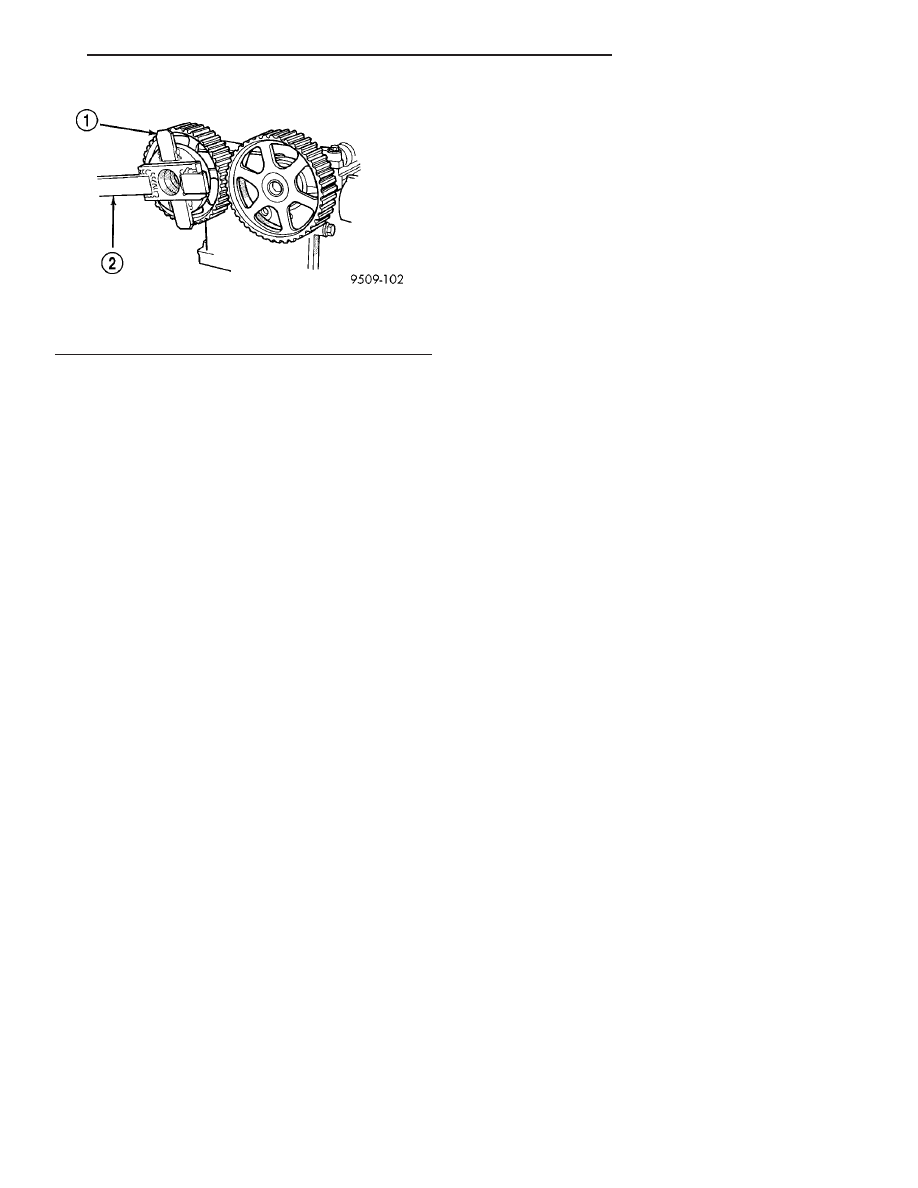
(2) Install
camshaft
sprockets.
While
holding
sprockets with Special Tools C-4687 and Adaptor
C-4687-1 (Fig. 109), tighten attaching bolts to 115
N·m (85 ft. lbs.).
(3) Install timing belt idler pulley.
(4) Install timing belt tensioner assembly (Refer to
9 - ENGINE/VALVE TIMING/TIMING BELT TEN-
SIONER & PULLEY - INSTALLATION).
(5) Install timing belt (Refer to 9 - ENGINE/
VALVE TIMING/TIMING BELT AND SPROCKETS -
INSTALLATION).
(6) Install front cover.
FRONT COVER
(1) Install front cover and tighten bolts to 12 N·m
(105 in. lbs.).
(2) Install engine front engine mount bracket (Fig.
108).
(3) Install right side engine mount (Refer to 9 -
ENGINE/ENGINE MOUNTING/RIGHT MOUNT -
INSTALLATION).
(4) Remove jack from under engine.
(5) Install generator bracket and generator. Recon-
nect generator connectors.
(6) Install accessory drive belt automatic tensioner.
(7) Install the crankshaft damper (Refer to 9 -
ENGINE/ENGINE BLOCK/VIBRATION DAMPER -
INSTALLATION).
(8) Install accessory drive belts (Refer to 7 -
COOLING/ACCESSORY
DRIVE/DRIVE
BELTS
-
INSTALLATION).
(9) Install accessory drive belt splash shield and
right front wheel.
(10) Connect negative battery cable.
Fig. 109 Camshaft Sprocket - Removal/Installation
1 - ADAPTER C-4687–1
2 - SPECIAL TOOL C-4687
JR
ENGINE 2.0L DOHC
9 - 67
TIMING BELT COVER(S) (Continued)