Chrysler Sebring, Stratus sedan, Sebring Convertible. Manual - part 356
WIPER BLADES
REMOVAL
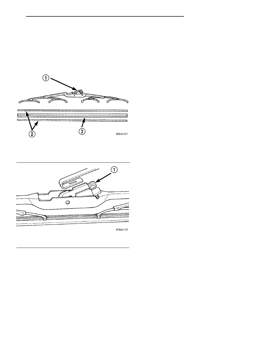
(1) Lift wiper arm to raise blade off glass.
(2) Remove blade assembly from arm by pushing
release tab under arm tip and slide blade away from
arm tip (Fig. 4) and (Fig. 5).
(3) The driver’s side wiper blade has a air foil on it
and the air foil points downward.
(4) Gently place wiper arm tip on windshield.
CLEANING
Wiper blades exposed to the weather for a long
period of time tend to lose their wiping effectiveness.
Periodic cleaning of the wiper blade is recommended
to remove the accumulation of salt and road grime.
The wiper blades, arms and windshield should be
cleaned with a sponge or cloth and a mild detergent
or nonabrasive cleaner. If the wiper blades continue
to streak or smear, they should be replaced. The
wiper blade should run smoothly across the wind-
shield in both directions. The wiper blade should
slightly roll over center when the blade reverses
direction. A wiper blade insert that has lost flexibility
or a wiper arm that has lost spring tension, will
cause the blade to skip or chatter across the wind-
shield. If the wiper blades are new and the wiper
arm spring tension is OK and a chattering sound is
emitted from the wiper(s), the wiper blade is not roll-
ing over center. If this condition exists, refer to the
Wiper Arm Alignment paragraph of this group.
INSTALLATION
(1) Gently lift the wiper arm tip off windshield.
(2) The driver’s side wiper blade has a air foil on it
and the air foil points downward.
(3) Install the blade assembly onto the wiper arm
by firmly snapping it onto the arm tip (Fig. 4) and
(Fig. 5).
(4) Lower blade to glass
(5) When complete turn ignition switch ON. Turn
wiper switch OFF allowing the wiper blades to
PARK. Then turn ignition switch OFF.
WIPER LINKAGE
REMOVAL
(1) Remove wiper arms and blades.
(2) Remove the cowl screen.
(3) Remove wiper motor assembly.
(4) Disconnect wiper arm linkage by using an ball
joint/tie rod separator. Separate the right and left
ball cap from the ball.
(5) Disconnect drive link from the motor crank.
Using an ball joint/tie rod separator and separate the
ball cap from the ball.
INSTALLATION
(1) Connect the drive link to the motor crank. If
motor output crank nut was removed, tighten nut to
25 to 30 N·m (19 to 23 ft. lbs.).
(2) Align link ball cap over ball and gently press
fit against shoulder of cap to lock cap into position.
(3) Install the wiper motor assembly.
(4) Install the cowl screen.
(5) Install the wiper arms.
WIPER MOTOR
REMOVAL
(1) Disconnect and isolate the battery negative
cable.
(2) Remove wiper motor assembly (Refer to 8 -
ELECTRICAL/WIPERS/WASHERS/WIPER
MOTOR
ASSEMBLY - REMOVAL).
Fig. 4 WIPER BLADE AND ELEMENT
1 - ARM RELEASE TAB
2 - VERTEBRA
3 - RUBBER ELEMENT
Fig. 5 REMOVE BLADE FROM ARM
1 - RELEASE TAB
JR
WIPERS/WASHERS
8R - 5