Chrysler Sebring, Stratus sedan, Sebring Convertible. Manual - part 353


  Index      Chrysler     Chrysler Sebring, Stratus sedan, Sebring Convertible - service repair manual 2001-2007 year


Search            


Content   ..  351  352  353  354   ..


Chrysler Sebring, Stratus sedan, Sebring Convertible. Manual - part 353


INSTALLATION

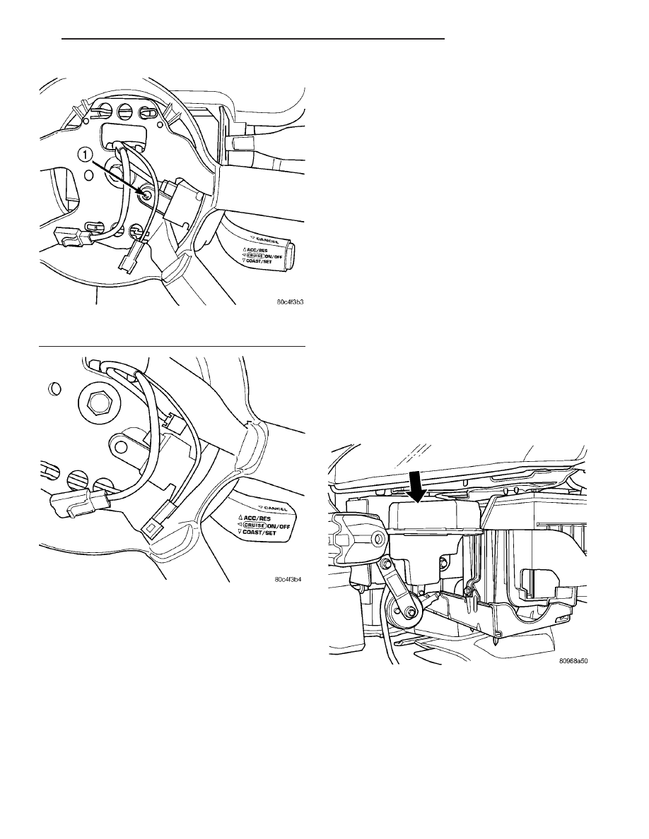
The speed control switch is mounted in the steer-

ing wheel and wired through the clock spring device
under the airbag module.

WARNING: IF REMOVAL OF AIRBAG MODULE IS
NECESSARY, REFER TO THE RESTRAINT SYS-
TEMS.

(1) Connect the electrical connector.
(2) Install switch (Fig. 6) and tighten the screws to

1.6 N·m (15 ins. lbs.). Make sure rubber seal is in
place around switch.

(3) Install airbag, refer to the Restraint Systems

section.

(4) Install the negative battery cable.

VACUUM RESERVOIR

DESCRIPTION

The vacuum reservoir is located under the left

front headlamp, in front of the battery. It is made of
plastic and does not contain any other parts, such as
a check valve.

OPERATION

The reservoir stores engine vacuum. Manifold vac-

uum is supplied from the brake booster check valve.
The speed control vacuum supply hose has a check
valve at the source (brake booster) to maintain the
highest available vacuum level in the servo, reservoir
and vacuum hoses. When engine vacuum drops, as in
climbing a grade while driving, the reservoir supplies
the vacuum needed to maintain proper speed control
operation. The vacuum reservoir cannot be repaired
and must be replaced if faulty.

REMOVAL

The vacuum reservoir is located below the left

front headlamp (Fig. 7).

(1) Remove the front fascia, refer to the Frames

and Bumper/Front Fascia section for more informa-
tion.

(2) Remove bolt from reservoir.
(3) Disconnect vacuum hose from reservoir.
(4) Remove the vacuum reservoir by sliding it up

slightly and seperating the nail head pegs (molded
into the reservoir) from the frame rail..

Fig. 5 Switch Top Mounting Screw

1 - TOP MOUNTING SCREW

Fig. 6 Switch Removal

Fig. 7 VACUUM RESERVOIR

JR

SPEED CONTROL

8P - 5

SWITCH (Continued)

INSTALLATION

(1) Connect vacuum hose to reservoir by inserting

nail head pegs on reservoir into the keyhole slots in
the frame rail and slide down to lock it into place.

(2) Install the vacuum reservoir (Fig. 7).

(3) Install bolt through to reservoir to frame rail.
(4) Install the front fascia, refer to the Frames and

Bumper/Front Fascia section for more information.

8P - 6

SPEED CONTROL

JR

VACUUM RESERVOIR (Continued)

VEHICLE THEFT SECURITY

TABLE OF CONTENTS

page

page

VEHICLE THEFT SECURITY

DESCRIPTION

. . . . . . . . . . . . . . . . . . . . . . . . . . 1

OPERATION

. . . . . . . . . . . . . . . . . . . . . . . . . . . . 1

DIAGNOSIS AND TESTING

DIAGNOSIS AND TESTING - SENTRY KEY

IMMOBILIZER SYSTEM . . . . . . . . . . . . . . . . . . 2

DIAGNOSIS AND TESTING - VEHICLE

THEFT SECURITY SYSTEM . . . . . . . . . . . . . . 3

TRANSPONDER KEY

DESCRIPTION

. . . . . . . . . . . . . . . . . . . . . . . . . . 3

OPERATION

. . . . . . . . . . . . . . . . . . . . . . . . . . . . 3

STANDARD PROCEDURE - TRANSPONDER

PROGRAMMING

. . . . . . . . . . . . . . . . . . . . . . . 4

VTSS/SKIS INDICATOR LAMP

DESCRIPTION

. . . . . . . . . . . . . . . . . . . . . . . . . . 5

OPERATION

. . . . . . . . . . . . . . . . . . . . . . . . . . . . 5

VEHICLE THEFT SECURITY

DESCRIPTION

VEHICLE THEFT SECURITY SYSTEM

The Vehicle Theft Security System (VTSS) is

designed to protect against whole vehicle theft. The
system monitors vehicle doors, decklid, and ignition
action for unauthorized operation. The alarm acti-
vates:

• Sounding of the horn

• Flashing of the park and tail lamps

• Flashing of the headlamps

SENTRY KEY IMMOBILIZER SYSTEM

The Sentry Key Immobilizer System (SKIS) is

available as a factory-installed option on this vehicle.
It is designed to provide passive protection against
unauthorized vehicle use by disabling the engine,
after two (2) seconds of running, whenever an invalid
key is used to start the vehicle. The SKIS is active
whenever the ignition is on and does not require any
customer intervention. The primary components of
the system are the Sentry Key Immobilizer Module
(SKIM), Sentry Key (ignition key w/ a transponder
molded into the head), indicator light, Body Control
Module (BCM), and the Powertrain Control Module
(PCM). The SKIM is mounted to the steering column
with the molded, integral antenna mounted on the
light halo surrounding the ignition lock cylinder. The
indicator light, is located in the message center.

OPERATION

VEHICLE THEFT SECURITY SYSTEM

Upon failure of proper Sentry Key Immobilizer

Module (SKIM) communication to the Powertrain
Control Module (PCM), the PCM will shut off fuel
after two seconds of run time. The engine will not

start on the key cycle that the failure occurred, a full
key down sequence must be performed for the engine
to crank again. After six consecutive fuel shut-offs,
the engine will no longer crank on subsequent key
cycles. The failure must be corrected and a valid
communication process between the SKIM and the
PCM must occur for the engine to crank and start
again.

The electronics for the Vehicle Theft Security Sys-

tem (VTSS) are part of the Body Control Module
(BCM). The system is armed when the vehicle is
locked using the:

• Power door lock switches (with any door ajar)

• Remote Keyless Entry transmitter.

• Door Cylinder Lock Switches.
For vehicles equipped with SKIS, the doors do not

have to be locked to enable the fuel shut off feature.

After the vehicle is locked and the last door is

closed, the LED indicator in the cluster will flash
quickly for 16 seconds, indicating that arming is in
progress. If no monitored systems are activated dur-
ing this period, the system will arm. The LED will
extinguish unless the decklid is open. If the decklid
is open, the LED will flash at a slower rate. This
indicates that the system is armed.

If fault is detected on any key cylinder input, the

LED indicator will remain solid during the arming
process, although the system will still arm. If the
indicator LED does not illuminate at all upon door
closing it indicates that the system is not arming.

Passive disarming occurs upon normal vehicle

entry by unlocking either door with the ignition key/
remote transmitter. This disarming will also halt the
alarm once it has been activated.

A tamper alert exists to notify the driver that the

VTSS had been activated. This alert consists of 3
horn pulses when the vehicle is disarmed.

JR

VEHICLE THEFT SECURITY

8Q - 1

NOTE: The VTSS will not arm by pushing down the
door lock mechanism. This will manually override
the system.

For Door Cylinder Lock Switch Removal and

Installation, refer to Electrical, Power Locks, Door
Cylinder Lock Switch, Removal, and Installation.

If the VTSS is triggered, the horn will pulse, head-

lamps/marker lamps will flash, and the VTSS warn-
ing lamp will flash. If the BCM determines the
threat to be false and the VTSS is not triggered
again, the system will shut down and rearm itself
after three minutes. If a trigger is still active, the
alarm will continue for an additional 15 minutes
without the horn. The VTSS monitoring portion of
the system is split into two sections.

ARMING THE VTSS

(1) With the key removed from the ignition lock

and any door open (excluding decklid), actuate one of
the following:

• Power door lock button to LOCK,

• Key fob LOCK button

• Door lock key cylinder to locked position.
(2) Close all opened doors. decklid can remain

open.

NOTE: If the decklid is open, it will not be secure.
Once the decklid is closed, a separate 16 second
counter will start. Once 16 seconds has been
reached, the decklid will then be secure, providing
a VTSS disarm request has not been received dur-
ing the 16 second decklid arming period.

(3) After the last door is closed, an arming time-

out period of sixteen seconds will start, then the
VTSS will become armed.

(4) If a 16 second time-out sequence was in process

and a new arm signal was actuated, the 16 second
time-out will restart from the time of the second
actuation.

If the LED indicator does not illuminate at all

upon final door closure, it indicates that the system
is not arming.

The current VTSS status armed or disarmed shall

be maintained in memory to prevent battery discon-
nects from disarming the system.

TRIGGERING THE VTSS

After the VTSS is armed, the following actions will

trigger the alarm:

• Opening any door.

• Turning the ignition to the ON, ACC, or

UNLOCK position.

• Opening decklid without first receiving a RKE

input or decklid key input.

CAUTION: The VTSS indicator LED will trigger and
engine will continue to run if the vehicle is
equipped with SKIS and the proper key is used to
start the vehicle. This condition will occur if the
VTSS has been triggered. If valid key is used, VTSS
will disarm

SENTRY KEY IMMOBILIZER SYSTEM

The SKIS includes keys from the factory which are

pre-programmed. Each SKIM will recognize a maxi-
mum of eight Sentry Keys. If the customer would
like to own additional keys other than those provided
with the vehicle, they can be purchased from any
authorized dealer. These keys must be programmed
to the SKIM on the vehicle in order for the system to
recognize them as valid keys. This can be done by
the dealer with a DRB III

t scan tool or by a cus-

tomer if this feature is available in their market and
they have two (2) valid keys already available to
them. Refer to the Service Procedures portion of this
system for additional details. The SKIS performs a
self-test each time the ignition switch is turned to
the ON position and will store Diagnostic Trouble
Codes (DTC’s) if a system malfunction is detected.
The SKIS can be diagnosed and any stored DTC’s
can be retrieved using a DRB III

t scan tool as

described in the appropriate Body Diagnostic Proce-
dures manual.

DIAGNOSIS AND TESTING

DIAGNOSIS AND TESTING - SENTRY KEY
IMMOBILIZER SYSTEM

WARNING: ON VEHICLES EQUIPPED WITH AIR-
BAGS,

REFER

TO

ELECTRICAL,

RESTRAINTS,

WARNINGS, BEFORE ATTEMPTING COMPONENT
DIAGNOSIS OR SERVICE. FAILURE TO TAKE THE
PROPER PRECAUTIONS COULD RESULT IN ACCI-
DENTAL AIRBAG DEPLOYMENT AND POSSIBLE
PERSONAL INJURY.

NOTE: The following tests may not prove conclu-
sive in the diagnosis of this system. The most reli-
able, efficient, and accurate means to diagnose the
Sentry Key Immobilizer System involves the use of
a DRB III

T

scan tool. Refer to the proper Body Diag-

nostic Procedures manual.

The Sentry Key Immobilizer System (SKIS) and

the Programmable Communication Interface (PCI)
bus network should be diagnosed using a DRB III

t

scan tool. The DRB III

t will allow confirmation that

the PCI bus is functional, that the Sentry Key Immo-

8Q - 2

VEHICLE THEFT SECURITY

JR

VEHICLE THEFT SECURITY (Continued)


Content   ..  351  352  353  354   ..