Chrysler Sebring, Stratus sedan, Sebring Convertible. Manual - part 352


  Index      Chrysler     Chrysler Sebring, Stratus sedan, Sebring Convertible - service repair manual 2001-2007 year


Search            


Content   ..  350  351  352  353   ..


Chrysler Sebring, Stratus sedan, Sebring Convertible. Manual - part 352


SPEED CONTROL

TABLE OF CONTENTS

page

page

SPEED CONTROL

DESCRIPTION

DESCRIPTION

. . . . . . . . . . . . . . . . . . . . . . . . 1

INTERACTIVE SPEED CONTROL

. . . . . . . . . . 1

OPERATION

. . . . . . . . . . . . . . . . . . . . . . . . . . . . 2

SPECIFICATIONS - TORQUE

. . . . . . . . . . . . . . . 3

SERVO

DESCRIPTION

. . . . . . . . . . . . . . . . . . . . . . . . . . 3

OPERATION

. . . . . . . . . . . . . . . . . . . . . . . . . . . . 3

REMOVAL

. . . . . . . . . . . . . . . . . . . . . . . . . . . . . 4

INSTALLATION

. . . . . . . . . . . . . . . . . . . . . . . . . . 4

SWITCH

REMOVAL

. . . . . . . . . . . . . . . . . . . . . . . . . . . . . 4

INSTALLATION

. . . . . . . . . . . . . . . . . . . . . . . . . . 5

VACUUM RESERVOIR

DESCRIPTION

. . . . . . . . . . . . . . . . . . . . . . . . . . 5

OPERATION

. . . . . . . . . . . . . . . . . . . . . . . . . . . . 5

REMOVAL

. . . . . . . . . . . . . . . . . . . . . . . . . . . . . 5

INSTALLATION

. . . . . . . . . . . . . . . . . . . . . . . . . . 6

SPEED CONTROL

DESCRIPTION

DESCRIPTION

The speed control system is electronically con-

trolled and vacuum operated. The electronic control
is integrated into the Powertrain Control Module,
located on the left side of the engine compartment
next to the air cleaner. The controls are located on
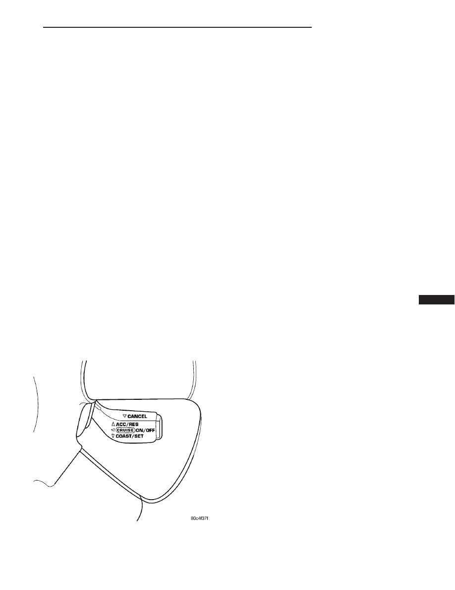
the steering wheel and consist of a single switch. The
ON, OFF, RESUME, ACCEL, SET, COAST, and
CANCEL, lever is located on the right of the steering
wheel (Fig. 1).

The system is designed to operate at speeds above

25 mph (40 km/h).

WARNING: THE USE OF SPEED CONTROL IS NOT
RECOMMENDED WHEN DRIVING CONDITIONS DO
NOT PERMIT MAINTAINING A CONSTANT SPEED,
SUCH AS IN HEAVY TRAFFIC OR ON ROADS THAT
ARE WINDING, ICY, SNOW COVERED, OR SLIP-
PERY.

INTERACTIVE SPEED CONTROL

DESCRIPTION

Interactive means that communication between the

PCM and the TCM is taking place, this communica-
tion is internal to the PCM on NGC vehicles. Inter-
active speed control avoids unnecessary shifting for
smoother, quieter operation and when downshifts are
required, makes the shifts smoother.

CLIMBING A GRADE

DESCRIPTION

When climbing a grade the interactive speed con-

trol tries to maintain the set speed by increasing the
throttle opening, while inability/delaying downshifts.

OPERATION

If opening the throttle alone cannot maintain the

set speed and the vehicle speed drops more than
three mph below the set speed, the transmission will
downshift. If the vehicle continues to lose speed, by
more than 6 mph, the transmission will downshift
again maintain the set speed. After the vehicle
encounters a less-steep grade, or has crested the
grade (reduced the load on the powertrain) and can
maintain the set speed at a reduced throttle position,
the transmission will upshift, as appropriate, until
the set speed can be maintained.

Fig. 1 Speed Control Switch

JR

SPEED CONTROL

8P - 1

DOWNSHIFT DELAY

DESCRIPTION

Downshift delay features have been added to

reduce the number and frequency of downshifts when
operating in hilly or mountainous country.

OPERATION

While operating, interactive speed control delays or

avoids downshifts by allowing up to nearly wide open
throttle without the TCM (on SBEC vehicles) (PCM
on NGC vehicles) scheduling a downshift. If the
interactive speed control is not engaged or the throt-
tle is manually overridden by the driver while inter-
active speed control is engaged, the downshift delay
feature is not activated.

Torque converter lock and unlock shifts are not

affected by the downshift delay feature and will occur
at the same throttle angle at a given speed regard-
less of whether interactive speed control operates or
not.

GRADE HUNTING

DESCRIPTION

All vehicles equipped with a four speed automatic

transmission have a grade hunting feature for the
2nd to 3rd gear upshift and the 3rd to Overdrive
upshift.

OPERATION

The TCM (on SBEC vehicles) (PCM on NGC vehi-

cles) identifies the powertrain loading conditions and
selects the proper gear to maintain the current vehi-
cle speed. Under moderate loading conditions the
transaxle will stay in 3rd gear until the top of the
grade is reached or the powertrain loading is
reduced.

If powertrain loading is severe, the transaxle may

shift into 2nd gear and remain there until power-
train loading is reduced, then a 2nd to 3rd gear
upshift will be scheduled. Grade hunting features
always operate regardless of whether or not the
interactive speed control is engaged. If the interac-
tive speed control is not engaged and power-
train loading is not reduced, the driver may
have to completely lift off of the throttle before
an upshift will occur
. If the driver does lift off the
throttle to induce an upshift under these conditions,
vehicle speed will reduce and the Overdrive to 3rd
and 3rd to 2nd gear downshifts will reoccur when the
throttle is reapplied. If grade hunting is repeatedly
induced by the driver, transaxle damage may result.

AUTOMATIC SPEED CONTROL OVERSPEED
REDUCTION

DESCRIPTION

Transmission control software includes an auto-

matic speed control overspeed reduction feature. This
maintains vehicle speed at the selected set point
when descending a grade.

OPERATION

The TCM (on SBEC vehicles) (PCM on NGC vehi-

cles) first senses that the speed control is set. If the
set speed is exceeded by more than 4 mph (6.5
km/hr) and the throttle is closed, the TCM (on SBEC
vehicles) (PCM on NGC vehicles) causes the trans-
axle to downshift to THIRD gear. After downshifting,
the automatic speed control resumes normal opera-
tion. To ensure that an upshift is appropriate after
the set speed is reached, the TCM (on SBEC vehi-
cles) (PCM on NGC vehicles) waits until the speed
control system opens the throttle at least 6 degrees
before upshifting to OVERDRIVE again.

If the driver applies the brakes, canceling auto-

matic speed control operation with the transaxle still
in THIRD gear, the TCM (on SBEC vehicles) (PCM
on NGC vehicles) maintains this gear until the driver
opens the throttle at least 6 degrees to avoid an inap-
propriate upshift. The upshift is also delayed for 2.5
seconds after reaching the 6 degrees throttle opening
in anticipation that the driver might open the throt-
tle enough to require THIRD gear. This will avoid
unnecessary and disturbing transmission cycling. If
the automatic speed control RESUME feature is used
after braking, the upshift is delayed until the set
speed is achieved to reduce cycling and provide bet-
ter response.

OPERATION

When speed control is activated by depressing the

ON switch, the PCM allows a set speed to be stored
in RAM for speed control. To store a set speed,
depress and release the SET switch while the vehicle
is moving at a speed between 30 and 85 mph. In
order for the speed control to engage, the brakes can-
not be applied, nor can the gear selector be indicat-
ing the transmission is in Park or Neutral (ATX) or
1st/2nd gear (MTX). The speed control can be disen-
gaged manually by:

• Stepping on the brake pedal

• Depressing the OFF switch

• Depressing the CANCEL switch.

• Depressing the clutch pedal

• Operating in 1st or 2nd gear (autostick, if

equipped)

8P - 2

SPEED CONTROL

JR

SPEED CONTROL (Continued)

NOTE: Turning the system off by depressing the
OFF switch or turning off the ignition switch will
erase the set speed stored in the PCM.

For added safety, the speed control system is pro-

grammed to disengage for any of the following condi-
tions:

• An indication of Park or Neutral

• A rapid increase rpm (indicates that the clutch

has been disengaged)

• Excessive engine rpm (indicates that the trans-

mission may be in a low gear)

• The speed signal increases at a rate of 10 mph

per second (indicates that the co-efficient of friction
between the road surface and tires is extremely low)

• The speed signal decreases at a rate of 10 mph

per second (indicates that the vehicle may have
decelerated at an extremely high rate)

• If the actual speed is greater than 20 mph over

the set speed.

• Autostick shifts into 1st or 2nd gear (autostick,

if equipped)

Once the speed control has been disengaged,

depressing the RESUME switch when speed is
greater than 20 mph allows the vehicle to resume
control to the target speed that was stored in the
PCM.

While the speed control is engaged, the driver can

increase the vehicle speed by depressing the ACCEL
switch. The new target speed is stored in the PCM
when the ACCEL switch is released. The PCM also
has

a

9tap-up9 feature in which target speed

increases by 2 mph for each momentary switch acti-
vation of the ACCEL switch. The PCM also provides
a means to decelerate to a new lower target speed
without disengaging speed control. Depress and hold
the COAST switch until the desired speed is reached,
then release the switch.

The PCM also has a “Tap Down” feature in which

target speed decreases at 1 mph for each momentary
switch activation of the coast switch.

SPECIFICATIONS - TORQUE

DESCRIPTION

N·m

Ft. Lbs.

In. Lbs.

Servo Mounting Bracket

Nuts

5.1

45

Servo Mounting Nuts

6.7

60

Vacuum Reservoir Screws

10.2

90

SERVO

DESCRIPTION

The servo unit consists of a solenoid valve body,

and a vacuum chamber. The solenoid valve body con-
tains three solenoids:

• Vacuum

• Vent

• Dump
The vacuum chamber contains a diaphragm with a

cable attached to control the throttle linkage.

OPERATION

The PCM controls the solenoid valve body. The

solenoid valve body controls the application and
release of vacuum to the diaphragm of the vacuum
servo. The servo unit cannot be repaired and is ser-
viced only as a complete assembly.

Power is supplied to the servo by the PCM through

the brake switch. The PCM controls the ground path
for the vacuum and vent solenoids.

The dump solenoid is energized anytime it receives

power. If power to the dump solenoid is interrupted,
the solenoid dumps vacuum in the servo. This pro-
vides a safety backup to the vent and vacuum sole-
noids.

The vacuum and vent solenoids must be grounded

by the PCM to operate. When the PCM grounds the
vacuum servo solenoid, the solenoid allows vacuum
to enter the servo and pull open the throttle plate
using the cable. When the PCM breaks the ground,
the solenoid closes and no more vacuum is allowed to
enter the servo. The PCM also operates the vent sole-
noid via ground. The vent solenoid opens and closes a
passage to bleed or hold vacuum in the servo as
required.

The PCM cycles the vacuum and vent solenoids to

maintain the set speed, or to accelerate and deceler-
ate the vehicle. To increase throttle opening, the
PCM grounds the vacuum and vent solenoids. To
decrease throttle opening, the PCM removes the
grounds from the vacuum and vent solenoids.

JR

SPEED CONTROL

8P - 3

SPEED CONTROL (Continued)

REMOVAL

(1) Disconnect the negative battery cable (Fig. 2).

(2) Remove 2 nuts attaching servo bracket to

shocktower.

(3) Disconnect electrical connectors and vacuum

hose.

(4) Remove two nuts attaching speed control cable

and mounting bracket to servo.

(5) Pull cable away from servo to expose retaining

clip and remove clip attaching cable to servo (Fig. 3).

(6) Remove servo mounting bracket.

INSTALLATION

(1) With throttle in full open position feed cable

sleeve through hole in bracket, then align hole in
speed control cable sleeve with hole in servo pin and
install retaining clip (Fig. 3).

(2) Connect vacuum hose to servo.
(3) Connect electrical connector.
(4) Insert servo studs through holes in speed con-

trol cable and mounting bracket (Fig. 3).

(5) Install nuts, tighten to 6.7 N·m (60 in. lbs.).
(6) Install servo and bracket to stud plate in

shocktower and tighten nuts.

(7) Connect negative battery cable (Fig. 2).

SWITCH

REMOVAL

The speed control switches is mounted in the steer-

ing wheel and wired through the clock spring device
under the airbag module (Fig. 4).

WARNING: IF REMOVAL OF AIRBAG MODULE IS
NECESSARY, REFER TO THE RESTRAINT SYS-
TEMS.

(1) Remove the negative battery cable.
(2) Turn off ignition.
(3) Remove air bag, refer to the Restraint systems

section.

(4) Remove the top mounting screw (Fig. 5).
(5) Rotate steering wheel so that the switch is in

the 6 o’clock position. Remove 2 screws from the back
side of the speed control switch.

(6) Disconnect the electrical connector.
(7) Remove switch (Fig. 6).

Fig. 2 NEGATIVE BATTERY CABLE

Fig. 3 SPEED CONTROL CABLE AND BRACKET

Fig. 4 Speed Control Switch

8P - 4

SPEED CONTROL

JR

SERVO (Continued)


Content   ..  350  351  352  353   ..