Chrysler Sebring, Stratus sedan, Sebring Convertible. Manual - part 314
 

  Index      Chrysler     Chrysler Sebring, Stratus sedan, Sebring Convertible - service repair manual 2001-2007 year


Search            


Content   ..  312  313  314  315   ..


Chrysler Sebring, Stratus sedan, Sebring Convertible. Manual - part 314


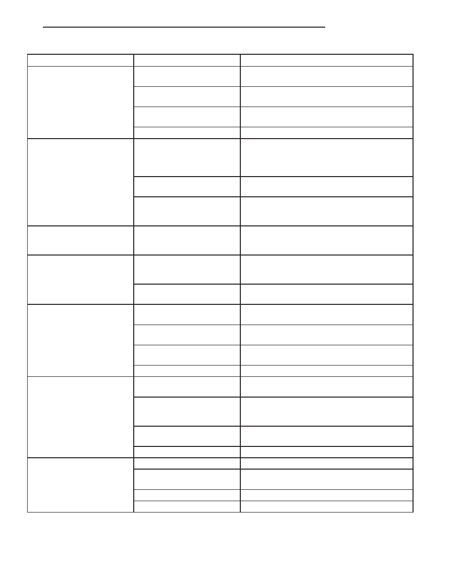
CONDITION

POSSIBLE CAUSES

CORRECTION

3. Wiring faulty between radio
and speaker.

3. Check wiring for open or short, repair wiring as
necessary.

4. Wiring faulty between radio
and amplifier.

4. Refer to speaker diagnostics. Repair wiring as
necessary.

5. Wiring faulty between
amplifier and speaker.

5. Wiring faulty between amplifier and speaker.

6. Amplifier faulty.

6. Replace amplifier.

SOUND DISTORTION
(VIBRATION FROM
SPEAKER AREA, BUZZING -
HUMMING)

1. Door trim panel loose or
missing fasteners.

1. Inspect door trim panel and correct as
necessary. Replace any missing fasteners.

2. Water shield loose or
misaligned.

2. Inspect water shield and adjust as required.

3. Items placed in door trim
panel map pockets vibrating
or moving from side to side.

3. Remove items from door trim panel. Ensure that
vibration is no longer present.

NO RADIO DISPLAY - AUDIO
AND CONTROLS ARE
OPERATIONAL

1. Radio faulty.

1. Refer to appropriate Diagnostic Service Manual.

NO RADIO DISPLAY - AUDIO
AND CONTROLS ARE NOT
OPERATIONAL

1. Fuse faulty.

1. Check radio fuse and Ignition-Off Draw (IOD)
fuse in Junction Block (JB). Replace fuses, if
required.

2. Radio connector faulty.

2. Check for loose or corroded radio connector.
Repair, if required.

CLOCK WILL NOT KEEP
SET TIME

1. Fuse faulty.

1. Check Ignition-Off Draw (IOD) fuse in the
Junction Block (JB). Replace fuse, if required.

2. Radio connector faulty.

2. Check for loose or corroded radio connector.
Repair, if required.

3. Wiring faulty.

3. Check for battery voltage at radio connector.
Repair wiring, if required.

4. Radio faulty.

4. Refer to appropriate Diagnostic Service Manual.

POOR RADIO RECEPTION
WITH KEY IN ACCESSORY
OR IGNITION ON POSTION

1. Antenna faulty.

1. (Refer to 8 - ELECTRICAL/AUDIO/ANTENNA
BODY & CABLE - DIAGNOSIS AND TESTING).

2. Radio ground faulty.

2. Check for continuity between radio chassis and
a known good ground. There should be continuity.
Repair ground, if required.

3. Radio noise suppression
faulty.

3. Repair or replace ground strap as necessary.

4. Radio faulty.

4. Refer to appropriate Diagnostic Service Manual.

NO/POOR TAPE
OPERATION

1. Faulty tape.

1. Insert known good tape and test operation.

2. Foreign objects behind
tape door.

2. Remove foreign objects and test operation.

3. Dirty cassette tape head.

3. Clean head with Mopar Cassette Head Cleaner.

4. Faulty tape deck.

4. Exchange or replace radio, if required.

JR

AUDIO/VIDEO

8A - 3

AUDIO (Continued)

2004 JR Service Manual
Publication No. 81-270-04025A
04JR8A-3

September, 2003

CONDITION

POSSIBLE CAUSES

CORRECTION

NO COMPACT DISC
OPERATION

1. Faulty CD.

1. Insert known good CD and test operation.

2. Foreign material on CD.

2. Clean CD and test operation.

3. Condensation on CD or
optics.

3. Allow temperature of vehicle interior to stabilize
and test operation.

4. Faulty CD player.

4. Refer to appropriate Diagnostic Service Manual.

AMPLIFIER

DESCRIPTION

The optional premium speaker system includes a

separate audio power amplifier. The amplifier is a
four channel unit and is rated at 120 (RCC sales
code) or a six channel rated at 150 (RCK sales code)
total output watts. The amplifier is located below the
front passenger seat.

OPERATION

The power amplifier electronically increases the

frequency response of the normal audio signal output
from the radio amplifier in order to improve the
acoustic performance of the speakers. On vehicles
equipped with an amplifier, the amplifier section of
the radio becomes a pre-amplifier.

The amplifier receives audio signal inputs for

speaker channels from the radio, then sends ampli-
fied audio outputs through six separate channels
with dedicated feed and return circuits to the indi-
vidual speakers.

REMOVAL

(1) Disconnect and isolate the battery negative

cable.

(2) Remove the retaining fasteners. Adjust or

remove the seat as necessary to gain access.

(3) Disconnect the wire harness connector.
(4) Remove the amplifier.

INSTALLATION

(1) Connect wire harness connector to amplifier.
(2) Install amplifier. Tighten the forward screw to

3 N·m (26.5 in. lbs.) and the rear nut to 2 N·m (18 in.
lbs.).

(3) Connect battery negative cable.

ANTENNA BODY & CABLE

DIAGNOSIS AND TESTING - ANTENNA BODY
AND CABLE

The following four tests are used to diagnose the

antenna with an ohmmeter:

• Test 1 - Coax cable at back of radio to ground

test

• Test 2 - Tip-of-mast to tip-of-conductor test

• Test 3 - Body ground to battery ground test

• Test 4 - Body ground to antenna coaxial cable

shield test.

WARNING:

DISABLE

THE

AIRBAG

SYSTEM

BEFORE ATTEMPTING ANY STEERING WHEEL,
STEERING COLUMN, SEAT BELT TENSIONER, SIDE
AIRBAG, OR INSTRUMENT PANEL COMPONENT
DIAGNOSIS OR SERVICE. DISCONNECT AND ISO-
LATE THE BATTERY NEGATIVE (GROUND) CABLE,
THEN WAIT TWO MINUTES FOR THE AIRBAG SYS-
TEM CAPACITOR TO DISCHARGE BEFORE PER-
FORMING FURTHER DIAGNOSIS OR SERVICE. THIS
IS THE ONLY SURE WAY TO DISABLE THE AIRBAG
SYSTEM. FAILURE TO TAKE THE PROPER PRE-
CAUTIONS COULD RESULT IN ACCIDENTAL AIR-
BAG DEPLOYMENT AND POSSIBLE PERSONAL
INJURY.

The ohmmeter test lead connections for each test

are shown in the illustration (Fig. 1).

NOTE: This model has a two-piece antenna coaxial
cable. Tests 2 and 4 must be conducted in two
steps to isolate an antenna cable problem. First,
test the primary antenna cable (integral to the body
wiring) from the coaxial cable connector just in
front of the front seat crossmember of the passen-
ger seat to the antenna body. Then, test the second-
ary antenna cable (instrument panel antenna cable)
from the coaxial cable connector just in front of the
front seat crossmember of the passenger seat to
the coaxial cable connector at the radio.

TEST 1

Test 1 checks the antenna conductor components

for a short circuit. This test should be performed first
on the entire antenna circuit, from the antenna mast
to the center conductor of the coaxial cable connector
at the radio. If a short circuit is detected, each of the
three antenna conductor components (antenna mast,
antenna body and primary cable unit, instrument
panel antenna secondary cable) should be isolated

8A - 4

AUDIO/VIDEO

JR

AUDIO (Continued)

2004 JR Service Manual
Publication No. 81-270-04025A
04JR8A-4

September, 2003

and tested individually to locate the exact component
that is the source of the short circuit. To begin this
test, proceed as follows:

(1) Disconnect the instrument panel (secondary)

antenna cable coaxial connector from the back of the
radio.

(2) Touch one ohmmeter test lead to the shield

ground of the coaxial cable. Touch the other test lead
to the center conductor pin of the instrument panel
antenna cable coaxial connector for the radio. Check
the ohmmeter reading for continuity.

(3) There should be no continuity. The ohmmeter

should register an open circuit. Low resistance indi-
cates a damaged or shorted antenna conductor. If
OK, go to Test 2. If not OK, isolate and test each of
the

individual

antenna

conductor

components.

Replace only the faulty antenna conductor compo-
nent.

TEST 2

Remove antenna mast or unplug antenna

cable to perform this test.

Test 2 checks the antenna conductor components

for an open circuit. This test should be performed
first on the entire antenna circuit, from the antenna
mast to the center conductor of the coaxial cable con-
nector at the radio. If an open circuit is detected,
each of the three antenna conductor components
(antenna mast, antenna body and primary cable unit,
instrument panel antenna secondary cable) should be
isolated and tested individually to locate the exact
component that is the source of the open circuit. To
begin this test, proceed as follows:

(1) Disconnect the instrument panel (secondary)

antenna cable coaxial connector from the back of the
radio.

(2) Touch one ohmmeter test lead to the tip of the

antenna mast. Touch the other test lead to the center
conductor pin of the instrument panel antenna cable

coaxial connector for the radio. Check the ohmmeter
reading for continuity.

(3) There should be continuity. The ohmmeter

should register only a fraction of an ohm resistance.
High or infinite resistance indicates a damaged or
open antenna conductor. If OK, go to Test 3. If not
OK, isolate and test each of the individual antenna
conductor

components.

Replace

only

the

faulty

antenna conductor component.

TEST 3

Test 3 checks the condition of the vehicle body

ground connection. To begin this test, proceed as fol-
lows:

(1) This test must be performed with the battery

positive cable disconnected from the battery. Discon-
nect and isolate both battery cables, negative cable
first.

(2) Reconnect the battery negative cable.
(3) Touch one ohmmeter test lead to a good clean

ground point on the vehicle fender. Touch the other
test lead to the battery negative terminal post. Check
the ohmmeter reading for continuity.

(4) There should be continuity. The ohmmeter

should register less than one ohm resistance. High or
infinite resistance indicates a loose, corroded, or
damaged connection between the battery negative
terminal and the vehicle body. If OK, go to Test 4. If
not OK, check the battery negative cable connection
to the vehicle body and the radio noise suppression
ground strap connections to the engine and the vehi-
cle body for being loose or corroded. Clean or tighten
these connections as required.

TEST 4

Test 4 checks the condition of the connection

between the antenna coaxial cable shield and the
vehicle body ground as follows:

(1) Disconnect and isolate the antenna coaxial

cable connector just in front of the front seat cross-
member of the passenger seat.

(2) Touch one ohmmeter test lead to a good clean

ground point on the vehicle fender. Touch the other
test lead to the outer crimp on the antenna coaxial
cable connector just in front of the front seat cross-
member of the passenger seat. Check the ohmmeter
reading for continuity.

(3) There should be continuity. The ohmmeter

should register less than one ohm resistance. High or
infinite resistance indicates a loose, corroded, or
damaged connection between the antenna body and
the vehicle body or between the antenna body and
the antenna coaxial cable shield. If not OK, clean the
antenna body to fender mating surfaces and tighten
the antenna cap nut to specifications.

Fig. 1 ANTENNA TESTS - TYPICAL

JR

AUDIO/VIDEO

8A - 5

ANTENNA BODY & CABLE (Continued)

(4) Check the resistance again with an ohmmeter.

If the resistance is still more then one ohm, replace
the faulty antenna body and cable.

REMOVAL

(1) Disconnect and isolate the battery negative

cable.

(2) Pull the right side trunk liner aside.
(3) Remove antenna mast by unscrewing mast

from antenna body.

(4) Remove screw from mounting bracket.
(5) Pull antenna body down through the rubber

grommet.

(6) Unplug antenna lead from base of antenna

body.

INSTALLATION

(1) Insert antenna lead to base of antenna body.
(2) Push antenna body up through the rubber

grommet.

(3) Install screw into mounting bracket. Tighten

screw to 12 N·m (106 in. lbs.).

(4) Install antenna mast. Tighten to 12 N·m (106

in. lbs.) Ensure that the antenna mast is fully
seated on antenna base and that there is no gap
between the mast and base.

(5) Install trunk liner.
(6) Connect battery negative cable.

CD CHANGER

DESCRIPTION

The In-Dash CD Changer (if equipped) is located in

the instrument panel below the radio. The remote
changer does not use a cartridge or magazine for the
CD’s. Up to 6 CD’s can be directly loaded into this
unit, one at a time.

OPERATION

Due to its compact design, the CD changer can

carry out only one operation at a time. For example,
you can not load a new disc while playing another at
the same time. Each operation happens sequentially.

The radio unit provides control over all features of

the CD changer with the exception of the CD load
and eject functions, which are controlled by buttons
located on the front of the CD changer. All features
you would expect, such as Disc Up/Down, Track
Up/Down, Random and Scan are controlled by the
radio, which also displays all relevant CD changer
information on the radio display.

On JR27 models, the CD changer will not operate

with the ignition in the OFF position. With the igni-
tion OFF, CD’s can not be removed from the changer.

The CD changer contains a Load/Eject button and

an indicator LED for each of the six disc positions as
well as an illuminated disc opening. The individual
LED indicates whether a CD is currently loaded.
Pressing the Eject button will eject the disc presently
selected. If the chamber is currently empty, actuating
the Select button will position that chamber to
receive and load a new disc in that chamber.

REMOVAL

(1) Disconnect and isolate the battery negative

cable.

(2) Remove lower center trim bezel.
(3) Remove screws from radio.
(4) Remove screws from CD changer (Fig. 2).

(5) Remove CD changer from Instrument panel.
(6) Disconnect wire connector from CD changer.

INSTALLATION

(1) Connect wire harness connector to CD changer.
(2) Insert CD changer into instrument panel.

Make sure that bumper on back of changer is
inserted into instrument panel opening.

(3) Pull radio from instrument panel far enough to

reach behind. Pull CD changer cable through radio
opening while inserting changer into instrument
panel.

(4) Install radio.
(5) Install screws to radio and CD changer.
(6) Install lower center trim bezel.
(7) Connect battery negative cable.

Fig. 2 CD CHANGER

8A - 6

AUDIO/VIDEO

JR

ANTENNA BODY & CABLE (Continued)


Content   ..  312  313  314  315   ..