Chrysler Sebring, Stratus sedan, Sebring Convertible. Manual - part 313


  Index      Chrysler     Chrysler Sebring, Stratus sedan, Sebring Convertible - service repair manual 2001-2007 year


Search            


Content   ..  311  312  313  314   ..


Chrysler Sebring, Stratus sedan, Sebring Convertible. Manual - part 313


INSTALLATION - 2.7L

(1) Clean all sealing surfaces.
(2) Install water pump and gasket. Tighten mount-

ing bolts to 12 N·m (105 in. lbs.).

(3) Install timing chain guides, timing chain, and

timing chain cover (Refer to 9 - ENGINE/VALVE
TIMING/TIMING BELT/CHAIN AND SPROCKETS -
INSTALLATION).

(4) Reconnect negative battery cable.
(5) Fill cooling system (Refer to 7 - COOLING/EN-

GINE - STANDARD PROCEDURE).

WATER PUMP INLET TUBE

REMOVAL

REMOVAL - 2.0L

(1) Drain cooling system (Refer to 7 - COOLING/

ENGINE - STANDARD PROCEDURE).

(2) Raise vehicle on hoist.
(3) Remove Air Conditioning Compressor/Genera-

tor accessory drive belt (Refer to 7 - COOLING/AC-
CESSORY DRIVE/DRIVE BELTS - REMOVAL).

(4) Disconnect and remove generator.
(5) Remove generator bracket.
(6) Disconnect lower radiator hose and heater hose

from the inlet tube (Fig. 43).

(7) Remove fasteners that hold the inlet tube to

the block.

(8) Rotate inlet tube while removing from the

engine block (Fig. 43).

REMOVAL - 2.4L

(1) Drain cooling system (Refer to 7 - COOLING/

ENGINE - STANDARD PROCEDURE).

(2) Raise vehicle on hoist.
(3) Disconnect lower radiator hose and heater hose

from the inlet tube (Fig. 43).

(4) Remove fasteners that hold the inlet tube to

the block.

(5) Rotate inlet tube while removing from the

engine block (Fig. 43).

INSTALLATION

INSTALLATION - 2.0L

(1) Inspect the O-ring for damage before installing

the tube into the cylinder block (Fig. 43).

(2) Lube O-ring with coolant and install tube into

the cylinder block opening.

(3) Install fasteners and tighten to 12 N·m (105 in.

lbs.).

(4) Reconnect lower radiator hose and heater hose

to inlet tube (Fig. 43).

(5) Install generator bracket.
(6) Install generator, reconnect connectors.
(7) Install Air Conditioning Compressor/Generator

accessory drive belt (Refer to 7 - COOLING/ACCES-
SORY DRIVE/DRIVE BELTS - INSTALLATION).

(8) Lower vehicle.
(9) Fill cooling system (Refer to 7 - COOLING/EN-

GINE - STANDARD PROCEDURE).

INSTALLATION - 2.4L

(1) Inspect the O-ring for damage before installing

the tube into the cylinder block (Fig. 43).

(2) Lube O-ring with coolant and install tube into

the cylinder block opening.

(3) Install fasteners and tighten to 12 N·m (105 in.

lbs.).

(4) Reconnect lower radiator hose and heater hose

to inlet tube (Fig. 43).

(5) Lower vehicle.
(6) Fill cooling system (Refer to 7 - COOLING/EN-

GINE - STANDARD PROCEDURE).

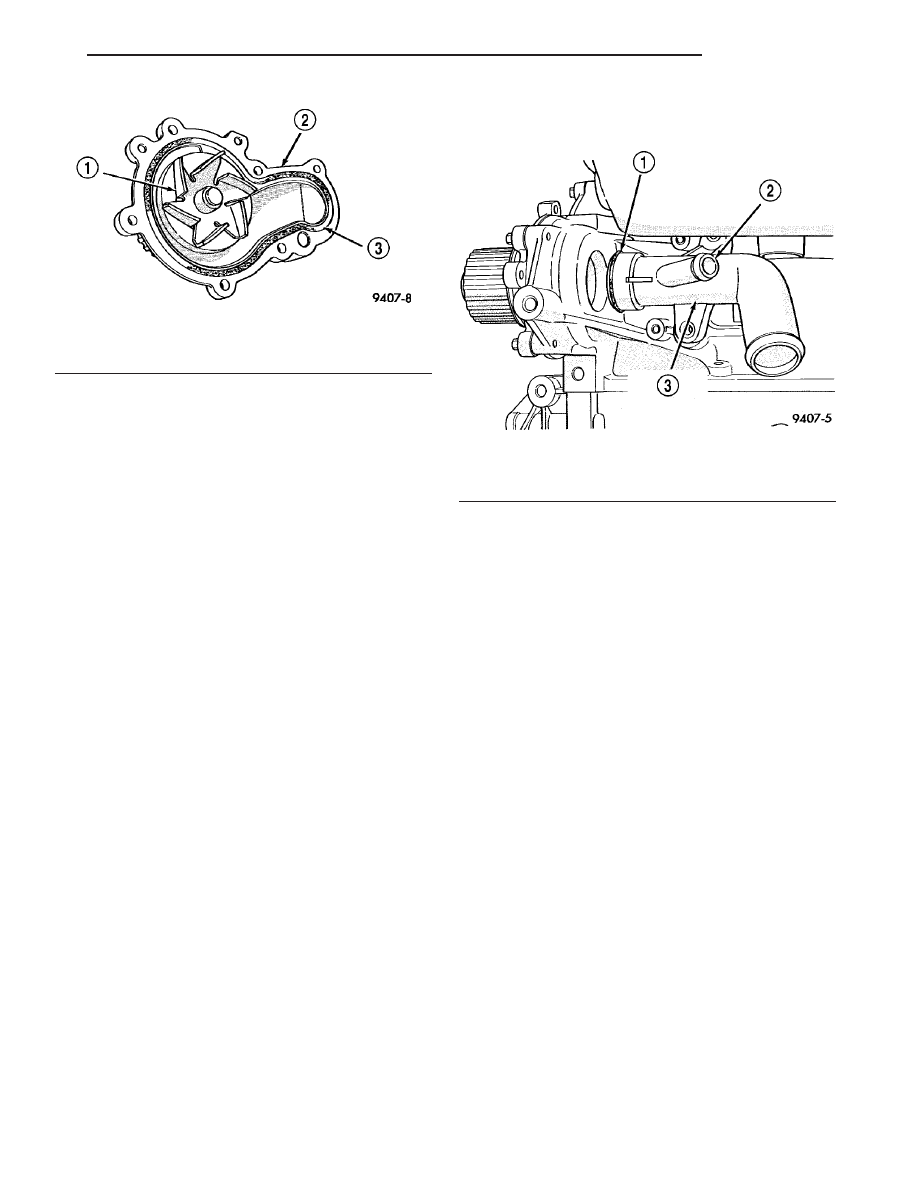
Fig. 42 Water Pump Body

1 - IMPELLER
2 - PUMP BODY
3 - O-RING

Fig. 43 Water Pump Inlet Tube - Typical

1 - O-RING
2 - TO HEATER
3 - WATER PUMP INLET TUBE

JR

ENGINE

7 - 45

WATER PUMP (Continued)

TRANSMISSION

TABLE OF CONTENTS

page

page

TRANSMISSION COOLER HOSES

DESCRIPTION

. . . . . . . . . . . . . . . . . . . . . . . . . 46

TRANSMISSION OIL COOLER

DESCRIPTION

. . . . . . . . . . . . . . . . . . . . . . . . . 46

OPERATION

. . . . . . . . . . . . . . . . . . . . . . . . . . . 46

REMOVAL

. . . . . . . . . . . . . . . . . . . . . . . . . . . . . 46

CLEANING

. . . . . . . . . . . . . . . . . . . . . . . . . . . . 46

INSPECTION

. . . . . . . . . . . . . . . . . . . . . . . . . . 46

INSTALLATION

. . . . . . . . . . . . . . . . . . . . . . . . . 46

TRANSMISSION COOLER
HOSES

DESCRIPTION

The transmission oil cooling circuit uses special

aggressive fittings for the transmission oil cooler
hoses. Whenever a transmission oil cooler hose is
removed from a transmission fitting (at transmis-
sion), it must be cut off flush with the fitting, and a
service splice kit must be used upon reassembly.
Refer to instructions provided with splice kit. When-
ever a transmission oil cooler hose is removed from a
transmission oil cooler tube (at transmission oil cool-
er), it must be replaced with a new hose. Removing
the hose from the aggressive fitting will scrape mate-
rial from inside the hose making the hose larger.
Failure to replace the hose or install a service splice
kit will result in transmission oil leaks.

When hose clamp replacement is necessary, replace

with the same type of hose clamp. Always use proper
hose clamp pliers on clamps. Use of improper hose
clamp pliers may bend hose clamps out-of-round
resulting in transmission oil leaks.

TRANSMISSION OIL COOLER

DESCRIPTION

An external oil-to-air type automatic transmission

oil cooler is mounted to the front of the radiator and
is integral to the A/C condenser (Fig. 1). The six
upper tubes are used for transaxle oil cooling, and
the remaining tubes below are for the A/C system.

The cooler uses tubes and rubber hoses to feed oil

to and from the automatic transaxle. The replaceable
inlet and outlet tubes use an O-ring for sealing. The
trans oil cooler is replaced with the A/C condenser.

OPERATION

The oil flows from the transmission to the oil-to-air

cooler. Heat is then transferred into the air.

REMOVAL

(1) Remove AC condenser(Refer to 24 - HEATING &

AIR CONDITIONING/PLUMBING/A/C CONDENSER -
REMOVAL).

CLEANING

Check the AC condenser for debris on the cooling

fin surfaces. Clean as necessary.

INSPECTION

Inspect all hoses, tubes, clamps and connections for

leaks, cracks, or damage. Replace as necessary. Use
only approved transmission oil cooler hoses that are
molded to fit the space available.

INSTALLATION

(1) Install AC condenser(Refer to 24 - HEATING &

AIR CONDITIONING/PLUMBING/A/C CONDENSER -
INSTALLATION).

Fig. 1 Transmission Oil Cooler

1 - AIR CONDITIONING CONDENSER/TRANSMISSION OIL COOLER
2 - TRANSMISSION OIL COOLER PORTION
3 - TRANSMISSION COOLER OUTLET
4 - TRANSMISSION COOLER INLET
5 - AIR CONDITIONING CONDENSER PORTION

7 - 46

TRANSMISSION

JR

AUDIO/VIDEO

TABLE OF CONTENTS

page

page

AUDIO

DESCRIPTION

. . . . . . . . . . . . . . . . . . . . . . . . . . 1

OPERATION

. . . . . . . . . . . . . . . . . . . . . . . . . . . . 1

DIAGNOSIS AND TESTING - AUDIO

. . . . . . . . . . 2

AMPLIFIER

DESCRIPTION

. . . . . . . . . . . . . . . . . . . . . . . . . . 4

OPERATION

. . . . . . . . . . . . . . . . . . . . . . . . . . . . 4

REMOVAL

. . . . . . . . . . . . . . . . . . . . . . . . . . . . . 4

INSTALLATION

. . . . . . . . . . . . . . . . . . . . . . . . . . 4

ANTENNA BODY & CABLE

DIAGNOSIS AND TESTING - ANTENNA BODY

AND CABLE

. . . . . . . . . . . . . . . . . . . . . . . . . . 4

REMOVAL

. . . . . . . . . . . . . . . . . . . . . . . . . . . . . 6

INSTALLATION

. . . . . . . . . . . . . . . . . . . . . . . . . . 6

CD CHANGER

DESCRIPTION

. . . . . . . . . . . . . . . . . . . . . . . . . . 6

OPERATION

. . . . . . . . . . . . . . . . . . . . . . . . . . . . 6

REMOVAL

. . . . . . . . . . . . . . . . . . . . . . . . . . . . . 6

INSTALLATION

. . . . . . . . . . . . . . . . . . . . . . . . . . 6

POWER ANTENNA - EXPORT

DIAGNOSIS AND TESTING - POWER

ANTENNA - EXPORT

. . . . . . . . . . . . . . . . . . . . 7

REMOVAL

. . . . . . . . . . . . . . . . . . . . . . . . . . . . . 7

INSTALLATION

. . . . . . . . . . . . . . . . . . . . . . . . . . 7

REMOTE SWITCHES

DESCRIPTION

. . . . . . . . . . . . . . . . . . . . . . . . . . 7

OPERATION

. . . . . . . . . . . . . . . . . . . . . . . . . . . . 8

DIAGNOSIS AND TESTING - REMOTE

SWITCHES

. . . . . . . . . . . . . . . . . . . . . . . . . . . 8

REMOVAL

. . . . . . . . . . . . . . . . . . . . . . . . . . . . . 9

INSTALLATION

. . . . . . . . . . . . . . . . . . . . . . . . . . 9

RADIO

DESCRIPTION

. . . . . . . . . . . . . . . . . . . . . . . . . 10

OPERATION

. . . . . . . . . . . . . . . . . . . . . . . . . . . 10

REMOVAL

. . . . . . . . . . . . . . . . . . . . . . . . . . . . . 10

INSTALLATION

. . . . . . . . . . . . . . . . . . . . . . . . . 10

SPEAKER

DESCRIPTION

. . . . . . . . . . . . . . . . . . . . . . . . . 11

OPERATION

. . . . . . . . . . . . . . . . . . . . . . . . . . . 11

DIAGNOSIS AND TESTING - SPEAKER

. . . . . . 11

REMOVAL

. . . . . . . . . . . . . . . . . . . . . . . . . . . . . 12

INSTALLATION

. . . . . . . . . . . . . . . . . . . . . . . . . 13

AUDIO

DESCRIPTION

Several

combinations

of

radio

receivers

and

speaker systems are offered. The audio system uses
an ignition switched source of battery current so that
the system will only operate when the ignition switch
is in the RUN or ACCESSORY positions.

The audio system includes the following compo-

nents:

• Antenna

• Power amplifier (with premium speaker system

only)

• Radio noise suppression components

• Radio receiver

• Remote radio switches (if equipped)

• Speakers
Certain functions and features of the audio system

rely upon resources shared with other electronic
modules in the vehicle over the Programmable Com-
munication Interface (PCI) bus network. The data
bus network allows the sharing of sensor informa-
tion. For diagnosis of these electronic modules or of
the data bus network, the use of a DRB III

t scan tool

and the proper Diagnostic Procedures manual are
recommended.

Refer to the appropriate wiring information for

complete standard and premium audio system circuit
diagrams. The wiring information includes proper
wire and connector repair procedures, further details
on wire harness routing and retention, as well as
pin-out and location views for the various wire har-
ness connectors, splices, and grounds.

OPERATION

The audio system components are designed to pro-

vide audio entertainment and information through
the reception, tuning and amplification of locally
broadcast radio signals in both the Amplitude Modu-
lating (AM) and Frequency Modulating (FM) com-
mercial frequency ranges.

The audio system components operate on battery

current received through a fuse in the Power Distri-
bution Center (PDC) on a fused ignition switch out-
put (run-acc) circuit so that the system will only
operate when the ignition switch is in the Run or
Accessory positions.

Refer to the owner’s manual for more information

on the features, use and operation of each of the
available audio systems.

JR

AUDIO/VIDEO

8A - 1

DIAGNOSIS AND TESTING - AUDIO

Any diagnosis of the Audio system should

begin with the use of the DRB III

diagnostic

tool. For information on the use of the DRB III

t,

refer to the appropriate Diagnostic Service Man-
ual.

For complete circuit diagrams, refer to the appro-

priate wiring information.

WARNING:

DISABLE

THE

AIRBAG

SYSTEM

BEFORE ATTEMPTING ANY STEERING WHEEL,
STEERING COLUMN, SEAT BELT TENSIONER, SIDE

AIRBAG, OR INSTRUMENT PANEL COMPONENT
DIAGNOSIS OR SERVICE. DISCONNECT AND ISO-
LATE THE BATTERY NEGATIVE (GROUND) CABLE,
THEN WAIT TWO MINUTES FOR THE AIRBAG SYS-
TEM CAPACITOR TO DISCHARGE BEFORE PER-
FORMING FURTHER DIAGNOSIS OR SERVICE. THIS
IS THE ONLY SURE WAY TO DISABLE THE AIRBAG
SYSTEM. FAILURE TO TAKE THE PROPER PRE-
CAUTIONS COULD RESULT IN ACCIDENTAL AIR-
BAG DEPLOYMENT AND POSSIBLE PERSONAL
INJURY.

AUDIO SYSTEM DIAGNOSIS

CONDITION

POSSIBLE CAUSES

CORRECTION

NO AUDIO AT ALL
SPEAKERS - RADIO
DISPLAY AND CONTROLS
ARE OPERATIONAL

1. Amplifier fuse faulty, if
equipped.

1. Check and replace fuses, if required.

2. Radio faulty.

2. Refer to appropriate Diagnostic Service Manual.

3. Wiring to amplifier faulty, if
equipped.

3. Verify radio on/off input to amplifier and verify
battery and ground connections. Repair wiring as
necessary.

4. Amplifier faulty, if equipped.

4. Replace amplifier.

NO AUDIO AT SOME
SPEAKERS - RADIO
DISPLAY AND CONTROLS
ARE OPERATIONAL

1. Radio faulty.

1. Refer to appropriate Diagnostic Service Manual.

2. Speaker(s) faulty.

2. Refer to speaker diagnostics.

3. Wiring faulty between radio
and speaker.

3. Check wiring for open or short, repair wiring as
necessary.

4. Wiring faulty between radio
and amplifier.

4. Refer to speaker diagnostics. Repair wiring as
necessary.

5. Wiring faulty between
amplifier and speaker.

5. Wiring faulty between amplifier and speaker.

6. Amplifier faulty.

6. Replace amplifier.

POOR AUDIO AT ALL
SPEAKERS - RADIO
DISPLAY AND CONTROLS
ARE OPERATIONAL

1. Radio faulty.

1. Refer to appropriate Diagnostic Service Manual.

2. Power/ground wiring open
or shorted.

2. Repair wiring as necessary.

3. Amplifier faulty.

3. Replace amplifier.

4. Power/ground wiring to
amplifier open or shorted.

4. Repair wiring as necessary.

POOR AUDIO AT SOME
SPEAKERS - RADIO
DISPLAY AND CONTROLS
ARE OPERATIONAL

1. Radio faulty.

1. Refer to appropriate Diagnostic Service Manual.

2. Speakers faulty.

2. Refer to speaker diagnostics.

8A - 2

AUDIO/VIDEO

JR

AUDIO (Continued)

2004 JR Service Manual
Publication No. 81-270-04025A
04JR8A-2

September, 2003


Content   ..  311  312  313  314   ..